Section 9: Flue System and Air SupplyPage 30
Table 9-4: White system components - product codes
Item 15-26 models 26-46 and 46-70 models
1.2 metre high level adjustable ue kit c/w 90° elbow and terminal HLK015090 HLK0290200
Adjustable vertical 3 metre ue kit c/w terminal and storm collar VTK055090 VTK0690200
225 mm extension EXTK31225/90 EXTK32225/200
450 mm extension EXTK09450/90 EXTK10450/200
950 mm extension EXTK11950/90 EXTK12950/200
275 to 450 mm adjustable extension EXTK13ADJ/90 EXTK14ADJ/200
45° elbow ELBK2145/90 ELBK2245/200
Pitched roof ashing - aluminium (VTK055090 and VTK0690200) VTMF200
Pitched roof ashing - lead VTK25P90 (includes collar)
VTK26P240 (no collar)
VTK26P200/X (includes collar)
Flat roof ashing - aluminium VTK27F90 VTK28F200
Wall bracket BRK2990 BRK30200
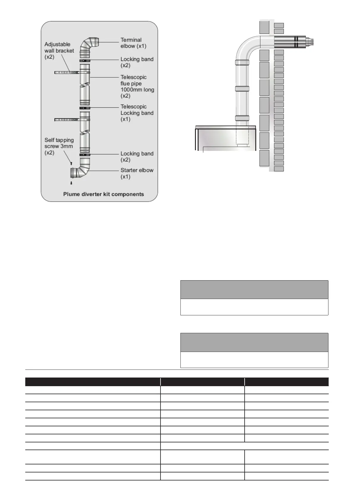
Figure 9-7: Yellow system Plume Diverter Kit
VERTICAL / HIGH LEVEL (HORIZONTAL)
BALANCED FLUE (WHITE SYSTEM)
VERTICAL SYSTEM
This version of the White system allows the ue to rise vertically
from the boiler to exit vertically through the roof by utilising a
vertical terminal with an integrated cowl.
The maximum ue length for this system - from the top of the
boiler ue outlet to the terminal - is 12 metres for all Grant Vortex
boilers.
HIGH LEVEL (HORIZONTAL) SYSTEM
This version of the White system allows the ue to rise vertically
within the building before exiting horizontally through the wall by
utilising a terminal with a 90° bend.
The maximum ue length for this system - from the top of the
boiler ue outlet to the outer face of the wall - is 10 metres for all
Grant Vortex boilers.
Refer to Figure 9-8 for a visual representation of the High Level
White system.
The following items are additionally available for BOTH versions
of the White system:
• Extensions to extend the ue by 225 mm, 450 mm or 950
mm.
• An adjustable extension of 275 to 450 mm.
• A 45° elbow - No more than 6 x 45° elbows should be tted
per system. Each elbow reduces the overall maximum length
of the system by 1 metre.
Two types of locking band are supplied with each kit, as follows:
• Type 1. A white painted band - for connecting xed joints
together, i.e. any joint that does not slide.
• Type 2. A white painted band - to cover the sliding joint on
the adjustable (telescopic) section.
! NOTE !
The locking band for the adjustable section is labelled for
easy identication.
Refer to Table 9-4 for a list of White system components and their
product codes.
! NOTE !
Only the terminal section of the White system is suitable
for external exposure.
Figure 9-8: High level balanced ue