! NOTE !
If the exible liners must pass around an oset inside
the chimney, deduct two metres of straight ue length to
compensate for this.
The Grant Red system exible stainless steel liner is directional.
The arrows marked on the inner liner MUST be pointing vertically
upwards, following the direction of the ue gases. Failure to
comply with this instruction could lead to a leakage of condensate
from the ue liner.
Flue extensions cannot be cut, use adjustable extensions where
required.
Three types of locking band are supplied with the kit, as follows
(Refer to Figure 9-9):
• Type 1. A white painted band - for connecting the white
painted ue sections that butt together, i.e. the joints with the
starter section and the rigid/exible adaptor.
! NOTE !
Two of this type of locking band are supplied in the kit.
Refer to Figure 9-9.
A single locking band of this type is supplied with every
additional elbow, extension kit or adjustable extension kit
used.
• Type 2. A white painted band - to cover the sliding joint on
the white painted adjustable (telescopic) section.
! NOTE !
The locking band for the adjustable section is labelled for
easy identication.
A single locking band of this type is supplied with every
additional adjustable extension kit used.
• Type 3. An unpainted stainless steel band - to secure the
outer of the two stainless steel ue liners to the white painted
rigid/exible adaptor.
The ue kit includes a Black coated terminal with upstand and is
designed to be xed (using the screws provided) to the top of a
masonry chimney.
The ue system may be oset using 45° elbows (product code:
ELBK2145/90 models up to 26 kW output).
No more than a maximum of four elbows should be used per
system.
EXTERNAL BALANCED FLUE
(GREEN SYSTEM)
Where it is not practical to use a low level (Yellow system) or
internal high level/vertical (White system) balanced ue, the
boiler can be tted with an external vertical/high level ue (Green
system).
See Figure 9-10.
The Starter kit ts to the boiler in the same way as a low level
balanced ue (Yellow system) and the external Tee allows the
connection of a twin wall insulated ue pipe and a combustion air
inlet - providing a room sealed ue system.
The external system can terminate at either high level or vertically
(above roof level) as required.
Up to three 45° elbows can be used in the vertical direction to
oset the ue around obstacles.
See Figure 9-10.
The minimum dimensions for locating the terminal from building
features (windows, doors, etc.) are shown in Figure 9-13.
The terminal must be positioned so as to avoid products of
combustion accumulating in stagnant pockets around the
buildings or entering into buildings. Care should be taken that the
plume from condensed ue gases does not cause a nuisance.
The components listed on the following page for the external ue
(Green system) components are available from Grant UK.
Section 9: Flue System and Air Supply Page 31
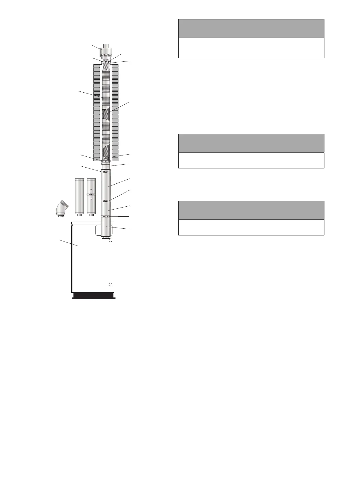
FLEXIBLE VERTICAL BALANCED FLUE (RED
SYSTEM)
Boiler
Flexible outer stainless steel liner
Terminal
Terminal upstand
Top plate
Support clamp
Rigid/flexible adaptor
Starter section
Telescopic flue (lower)
Telescopic flue (upper)
Locking band for
adjustable joint section
(Type 2)
Connector
Stainless Steel
Locking band
(Type 3)
Locking band
(Type 1)
Locking band
(Type 1)
Elbow, extension
and adjustable extension
from 'White' system
Flexible inner
stainless steel liner
The inner flue
liner is directional
(see Section 9.4)
Note:
Figure 9-9: Red system balanced ue (15-26 only)
This is a exible vertical balanced ue system (for the 15-26
models only) designed to be tted inside an existing masonry
chimney. See Figure 9-9.
It basically consists of three sections:
• Concentric white painted ue pipe connected to the boiler.
• The vertical concentric exible ue consists of a exible
stainless steel inner ue liner (directional) inside a exible
stainless steel outer ue liner.
• Terminal assembly for chimney top mounting.
The ue pipe seals are factory tted and must be lubricated with
the lubricant supplied before assembly.
The Red system is supplied as a separate kit. Flue extensions
and 45° elbows from the White system may be used to extend the
ue between the boiler and the exible section of the system.
The maximum vertical straight length of ue, from the top of the
boiler to the top of the terminal, is 20 metres – using no more than
four 45° elbows. Deduct 1 metre of straight ue length for every
elbow used.