CE5000-UM-251-9370 6-17
6 DISASSEMBLY AND REASSEMBLY
6.2.6 How to Replace the Push Roller Sensor
How to detach the push roller sensor
(1) Detach the center cover (see Subsection 6.1.3 or 6.1.4).
(2) Detachthepenblock(seeSubsection6.2.5).
(3) DisconnectthepushrollersensorexiblecablefromtheY-relayboard.
(4) Removethepushrollersensorexiblecablethatisattachedwithdouble-sidedadhesivetapetothe
Y-slider.
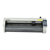
(5) RemovetheM3L6bindingheadscrewattachingthepushrollersensorbrackettotheslider.
Y-slider
M3L6 binding
head screw
Push roller sensor board
Push roller sensor bracket
(6) RemovetheM3L6bindingheadscrewattachingthepushrollersensorboard.
(7) Disconnectthepushrollersensorexiblecablefromthepushrollersensorboard.
How to reinstall the push roller sensor
(1) Attachthepushrollersensorbrackettothepushrollersensorboard.
(2) Connectthepushrollersensorexiblecabletothepushrollersensorboard.
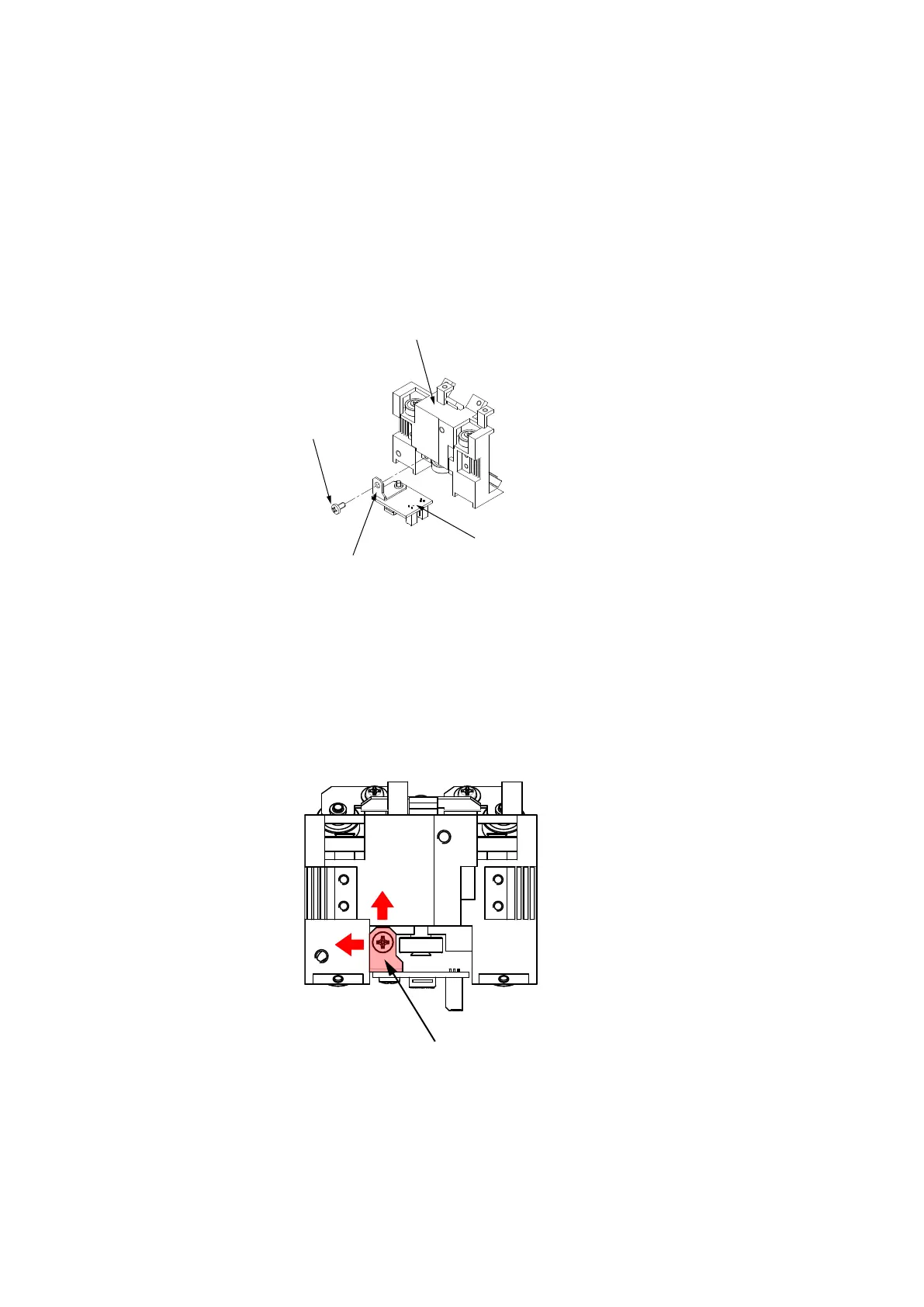
(3) AttachthepushrollersensorbrackettotheY-slider.
FitthetopandleftedgesofthepushrollersensorbrackettotheY-sliderasshowninthegurebelow.
Push roller sensor bracket
(4) Attachthepenblock(seeSubsection6.2.5).
(5) Reattachtheotherpartsinthereverseorderinwhichtheyweredetached.