JUPITER CM-4400 Control Module Installation and Operating Manual 305
Physical Serial Interface
Commands are repeated up to 3 times when a NAK (error) occurs.
Physical Serial Interface
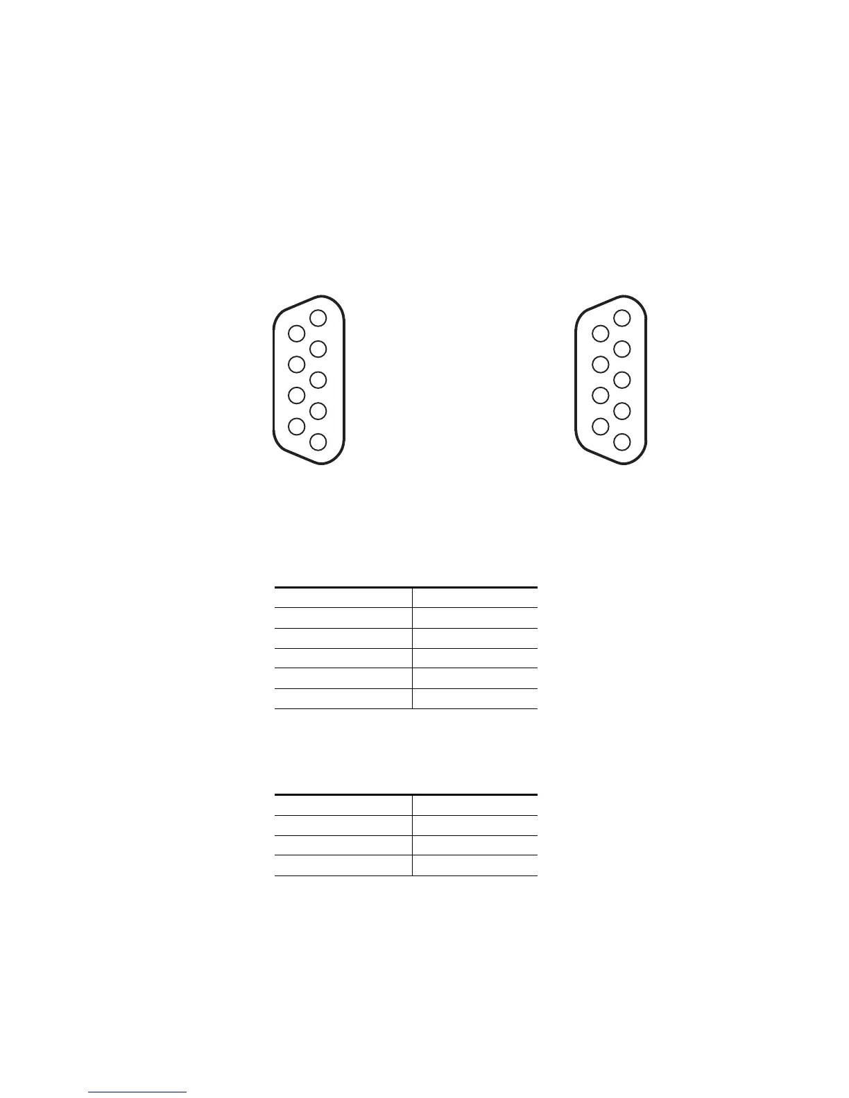
This section describes the pins of the Serial cable. The two Tables (Table 38
and Table 39) describe the configuration.
Figure 240. Serial Cable Pin-out
Table 38. Control Module RS-422/485 Female 9 pin Configuration
Pin # Configuration
1 GND
2 RX-
3TX+
7 RX+
8TX-
Table 39. PC RS-232 Male DTE pin Configuration
Pin # Configuration
5 GND
2 RXD
3TXD
071827512_Probell-Serial connections
1
6
R−
2
7
3
T−
8
4
9
5
R
RS-422/485
(female)
RS-232 DTE
(male)
1
6
2
7
3
8
4
9
5
T+
R+
G
G
T
 Loading...