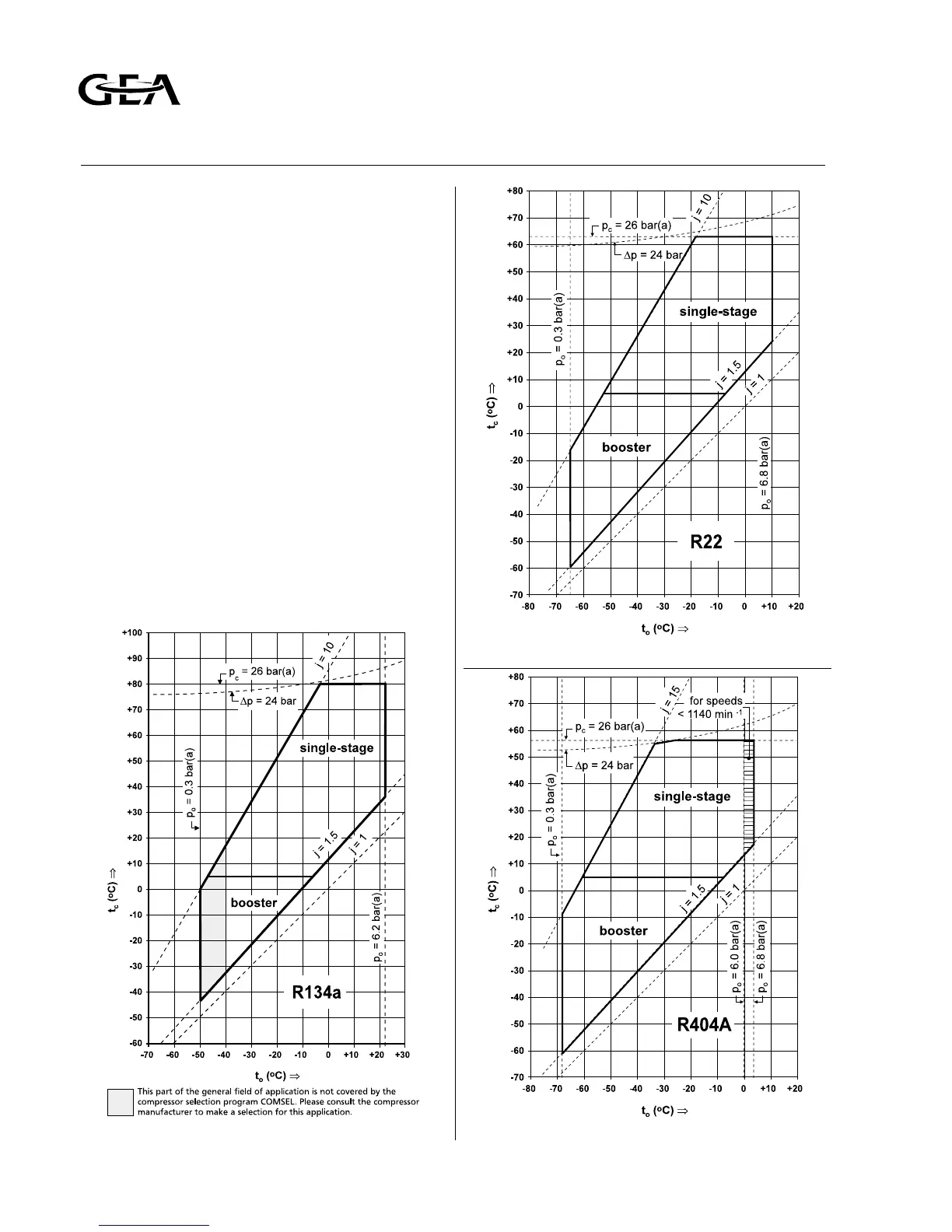
5.2 FIELDS OF APPLICATION FOR SINGLE-STAGE
AND BOOSTER OPERATION.
The following 5 diagrams, related to the refrigerants
R134a, R22, R404A and NH3 represent the fields of
application at continuous operation with different
conditions at any speed between 800 and
1500/min. In case of RC6 and booster application
the compressor manufactuer should be consulted. In
each diagram the area comprising all allowable
combinations of evaporating temperature t
o
and
condensing temperature t
c
(general field of
application) is enclosed by a broken bold line, of
which each line section corresponds to one of the
individual operation limits as stated in table 5.1.
Symbols used in diagrams:
t
o
= evaporating temperature
p
o
= evaporating pressure
t
c
= condensing temperature
p
c = condensing pressure
j = pressure ratio = (p
c
/p
o
)
∆p = pressure difference = (p
c
-p
o
)
∆t
o
= suction superheat
t
e
= discharge temperature in cylinder head covers
V
s
= part-load swept volume (= part-load capacity)
expressed in percentage of full-load (100%)
Fig. 5.2 Field of application for RC6 with refrigerant R22
Fig. 5.3 Field of application for RC6 with refrigerant R404AFig. 5.1 Field of application for RC6 with refrigerant R134a
Refrigeration Division
Grasso
5. LIMITS OF OPERATION AND
FIELDS OF APPLICATIONS
page C3.2 Installation and Maintenance Manual RC(U)6 v001.99.01.en