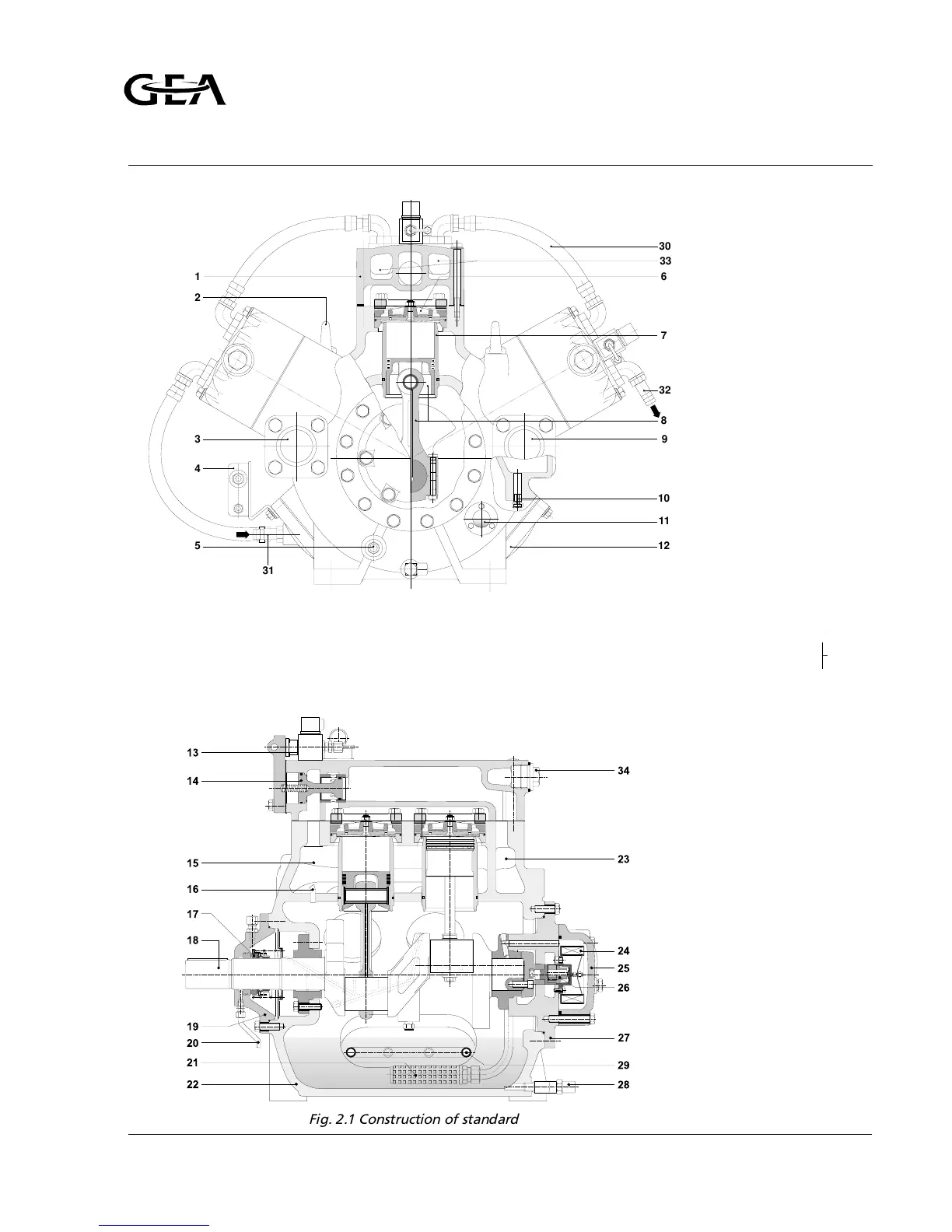
1. cylinder head cover
(water-cooled)
2. lifting eye
3. suction connection
4. oil differential pressure
safety switch (optional)
5. crankcase heater (optional)
6. suction and discharge
valve assembly
7. cylinder liner
8. piston and connecting rod
9. discharge connection
10. oil return check valve
11. sight glass
12. inspection side cover
13. 3-way solenoid valve
14. by-pass slide valve
15. suction chamber
16. tube for pressure equalizing
17. rotary shaft seal
18. crankshaft
19. shaft seal housing
20. oil leakage drain
21. oil suction filter
22. crankcase
23. discharge chamber
24. oil discharge filter
25. oil filter housing
26. oil pump
27. bearing cover
28. oil charge and drain valve
29. oil cooler (water-cooled)
30. cooling water hose
31. water inlet connection
32. water outlet connection
‘ 33. cast-in channel
for cooling water
34. Plug cooling water channel
1
33
2
3
4
5
6
7
8
32
30
31
9
10
11
12
Fig. 2.1 Construction of standard bare compressor (RC66W)
Refrigeration Division
Grasso
DESIGN DETAILS OF STANDARD
BARE COMPRESSOR
v001.99.01.en Installation and Maintenance Manual RC(U)6 page C4.1