new functions 15
If you want to set the offset into one of the two
controllers you will have to adjust it to –100% or
+100%.
2. PCM- and SPCM-receivers:
Due to the compression of data information in the
transmitter in PCM- and SPCM mode, is it possible
for servos connected to receiver outputs 9 and/or 10
to run with some “jitter“. (see also mc-24/1-operating
instructions Page 91.) This effect is especially
noticable on 6 wing servo models when the two
puts
ail type “normal“ and “V-tail“:
servos are to be controlled with the aileron control
stick( selectable in Code 71 »
Wing mixers«).
For this reason we recommend to connect the inner
camber flap servos (9+10) to the receiver out
1+8:
T
8
2 56
1
7
3
4
PCM
Bremsklappen oder Motordrossel
Wölbklappe rechts
Wölbklappe links
Seitenruder oder V-Leitw. rechts
Querruder links
Höhenruder oder V-Leitw. links
Querruder rechts
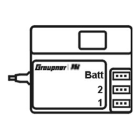
Batt
frei (Schleppkupplung)
Wölbklappe 2 links
9
8
7
6
10
Wölbklappe 2 rechts
5
4
3
2
1
PCM-Em
links
pfänger
Tail type “Delt/fl.wing“:
rechts
8
PCM
7
3
2
6
1
4
Bremsklappen oder Motordrossel
Wölbklappe rechts
Wölbklappe links
Seitenruder (links)
Querruder/Höhenruder links
Querruder/Höhenruder rechts
frei (Seitenruder rechts)
Batt
frei (Schleppkupplung)
Wölbklappe 2 links
9
8
7
6
5
4
3
2
1
Wölbklappe 2 rechts
10
PCM-Empfänger
Delt/fl.wing-models with two Rudders
See also adjustment procedure above in section
“1. PPM-receiver“.
Important notice:
In addition for both tail types with the described
connecting order you must select in Code 85
Servo 9 to output 1 and
o output 8
u have available
ke-flap or motor
control utilising the throttle/brake stick and
• move servo 8 to output 10, you can control a servo
connected to output 10 via a controller on input 8
(Code 32 »
Control adjust«) and use for a special
function.
»
RX.output swap«:
•
• Servo 10 t
If you apart from that...
• move servo 1 to output 9 yo
receiver output 9 for the use of bra
Without mixing, the servos connected to the two
outputs (9+10) will run “jitter“ free.
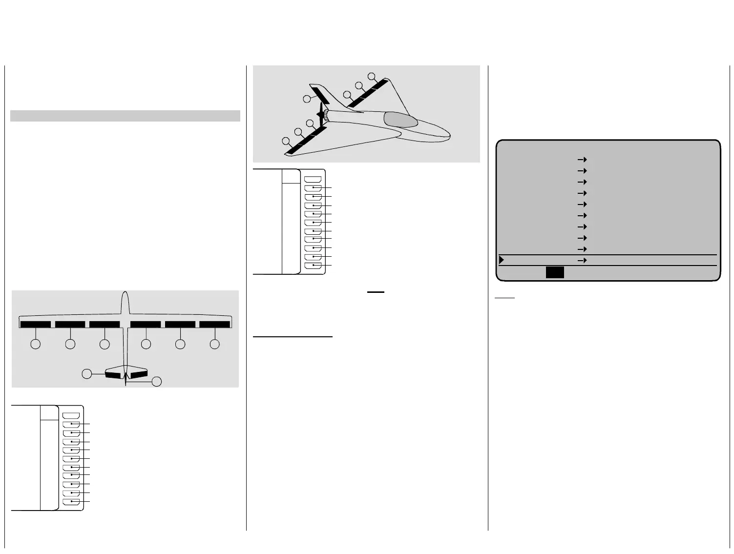
Code 85 »
Receiver output swap« must be
programmed as follows:
E M P F Ä N G E R A U S G A N G
Servo 9 Ausgang 1
Servo 2 Ausgang 2
Servo 3 Ausgang 3
rvo 4 Ausgang 4
rvo 5 Ausgang 5
Servo 7
Servo 10
Servo 1
Servo 8
Se
Se
Servo 6 Ausgang 6
Ausgang 7
Ausgang 8
Ausgang 9
Ausgang10
SE
L
Hint:
Select this “PC
if you use a PP
utputs..
i mc-
24/1 Page 107)
•
all changes m
Dual Rate/Ex
relation to the asic
setting!
•
Please note that when swopping receiver outputs
that the fail-safe programming for “stop“ or “pos“ in
SPCM20-mode to the receiver and batt. fail –safe
in PCM20-mode is fixed to outputs 1 / 8
M-connection“ for 6 wing servos also
M-receiver with only 8 or 9 Servo
o
Important not ce (see also instruction manual
:
ade at a later stage to servo travel,
po, mixer etc., have to be done in
receiver connections as in the b
 Loading...