new functions 31
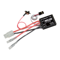
a) AILE - adjustments
In the landing approach the ailerons should both
move a little up with application of the brake
function.
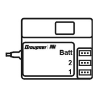
b) FLAP- and FLAP2 adjustments
During braking in the landing approach both f
pairs can be controlled indepen
lap
dantly i.e.:
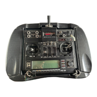
c) Crow -function
With the “Crow“ function both ailerons
Move up and all flaps move down.
This combination is used for control of
the approach angle during landing
(see hand book mc-24/1, page 76).
The employment of air brakes and/
mixer combinations as described (pa
a…c) normally call for some elevator
or the
ra
sation.
Especially with extreme “CROW“
positions can the effect of the ailerons be
deminished (see mc-24/1-hand book,
page 77). Here is now the possibility to
reduce the amount of differential with
increase of brake function. The Diff.-red.
Will also work on the ailerons if the model
has no flaps.
he
the new mc-24 PROFI-ROM-Software
works a little different.
to the right, than the left aileron down
deflection is reduced by an amount
selected in the multi-flap–menu (line
“Diff“). If now the inverse differential
starts to take an effect, the left (up)
deflection is enlarged and the right
(down) defection reduced.
Example
compen
This mixer is described further down.
Diff.-reduct.:
In the prior described multi- flap –
menu can a differential control be
selected for the three pairs of “FLAP“.
If the value for the differential
reduction is the same as for the
differential value i.e. diff = 40% and
the diff. Red. = 40% than t
differential is equalised (0%) exactly
when the brake control stick is at
max (back) position – also full brake.
If the differential reduction value is
higher than the differential value,
To be able to eliminate a mechanically
induced differential with the electronic –
an inverse differential:
If you for example move the aileron stick
: With an AILE diff. of 50% and a
diff. red. of 100% is the differential value
0% with the brake control stick (normal
channel 1 controller) exactly in the
middle. After that point the inverse
differential reduction (as described
above) begins.
The adjustment range is ±150%.
CLEAR = 0%.
The adjustment for any differential values
is best undertaken on the completed
model and/or in flight.
QR
WK
WK
QR
WK2
WK2
QR
WK
WK2
WK2
WK
QR
QR
WK
WK2
WK2
WK
QR
WK
WK2
WK2
WK
QR
QR
vorn
Bremse eingefahren
hinten
Bremse ausgefahren
 Loading...