TIP:
Of help during programming of the various flight
phases is the command “Copy flight phase“ in Code
1
y/erase meters of
phase are established and than copi he
odifie suit
2 »
cop «. First all para a flight
ed into t next
flight phase where they can be m d to the
new flying mode.
“Name“: Pres d use t tary
se he list fo re
pha 1 reserved
(ap mal na s)
reate your ow e 91
»B
to 7 is not critical and
•
in Code 52 no phase switch is set
on.
e
es are program neutral and serve
as identification only for the further
programming of flight phases and hence
they are displayed in all flight phase
dependant menus and in the default
display.
“Fl.ph.tim“: Apart from the normal timers in the
default display are a number of other
timers available. The adjustments for
these timers are to be found in Code
62
»Flight phase timers
«, Page 71 of the
mc-24/1-hand book.
Timer selection list:
s the SEL-key an he ro
control to cho a name from t r the quired
ses to 7. The name “Autorot“ is
on
for
the autorotati phase only.
You can art fr norom using the
n names in Cod
phase
asic
me
Tim 2
”Tim2“ stores the “OFF“ and the “ON“ time
s of the relevant switch i.e. the timer restart
d the counter with every switch action an
increases by one.
c
settings«.
The sequence of phases 1
does not have to be continuos. But you begin
always with “phase 1“ the “normal phase“ which is
always active when
• no switch combinations exist
• all phase switches are in default positi
The phase name “normal“ could therefor
be logical for “phase 1“.
The nam
Tim 1, Tim 2, Tim 3, Lap,
Tim 1,Tim 2.
While you can record lap times with the
h
d
A ey
w d
k
T
t
ll timers can be halted with the STOP-k
ithout activating the switch which woul
e and the cloc
timer “Lap“, by use of an auxiliary switc
the two new timers after that “Tim1“ an
“Tim2“ have the following meaning:
increse the counter by on
Tim2 restarts.
o be able to read the timer memory with
he rotary controller, you must first stop the
Application:
Timing of pure flight time if for example a
control switch on the CH1 controller is
activated by movement towards max pitch.
The adjustment for the switching point is
made in Code 42 »Control switch«.
“t
A
im2“ clock with the STOP -key
pplication
T over
fl
iming of normal flight and timing of h
ight.
CLEAR –
display to th
Notice:
resets the halted timers in the default
e start value.
with
transmitte
“Auto tim
With “YE
e
selected in
s are
Tim 1
Recording of time will only occur if in th
line “Lap tim/tim.tab“ a switch is
Code 62
»Flight phase timers« i.e. an
auxiliary, control or logical switch is in the
closed position. The number of switch
activations is indicated in the default
display. The indication of the counter
contrast inverse as soon as the switch for
tim1 has been “opened“ (the timer
stopped):
STOP
Please note that all timers will be reset
r switch-ON if you have enabled function
er reset“ in Code 21 > Base setup model<
S“.
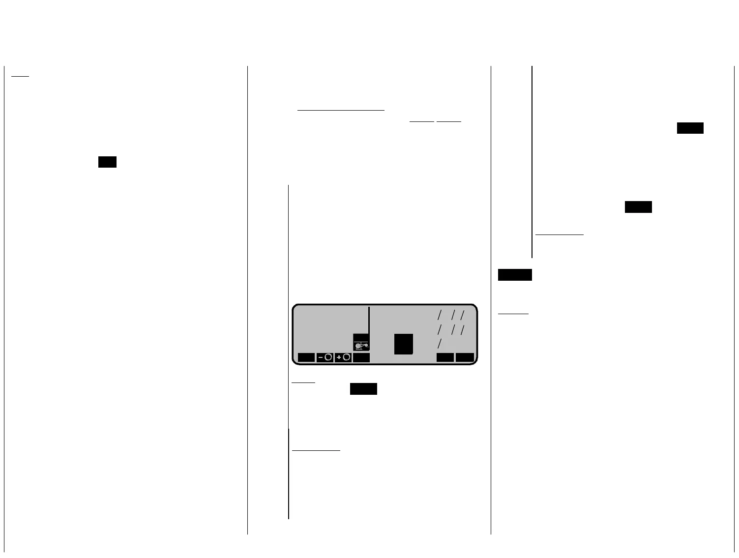
NH-90
Mod. 08 1:18h
U
A
we Corbach
kku 2:34h
9.8V
FNK
Stoppuhr
Flugzeit
0 00
0 00
RUN
M
0 3502
»
:
:
:
Zeit1
«Akro
OD
Note:
Als can the timer be
halted.
o with the STOP-key
new functions 24
With the rotary control you can check on
the switch symbols if neseccary.
 Loading...