Code 51
Phase adjust
Programming of flight phases
„Fl.ph.tim. “: Apart from
default display are a numb
new functions 23
the normal timers in the
er of other timers
available. The adjustment for these timers are to b
found in Code 62 »
Flight phase timers«, Page 71
of the mc-24/1-hand
e
se
book.
lection list:
Timer
m 2, Tim 3, Lap, Tim 1, Ti Tim1,
Tim2.
While you can record lap times with the
timer “Lap“ by use of an auxiliary switch,
the two new timers after that - “Tim1“ and
“Tim2“- have the following meaning:
Tim 1
Recording of time will only occur if in the
line “Lap tim/tim.tab“ a switch is selected
in Code 62
»flight phase timers« i.e. an
auxiliary, control or logical switch is in the
“closed“ position. The number of switch
activations is indicated in the default
display. The indication of the counters are
contrast inverted as soon as the switch for
tim1 has been “opened“ ( the timer
stopped ):
STOP
DV20 KATANA
Mod. 03 2:18h
Uwe Corbach
Akku 6:48h
9.8V
FNK
RUN
MOD
Stoppuhr
Flugzeit
Zeit1
0 00
0 00
0 3502
«Akro »
:
:
:
Application:
Timing of motor run if the same switch
Note:
Also with the STOP-key can the timer be
halted.
With the rotary control you can check on
the switch symbols if neseccary.
controls the motor.
Tim 2
„Tim2“ stores the “OFF“ and the “ON“ time
of the relevant switch i.e. the timer restarts
with every switch action and the counter
increases by one.
All timers can be halted with the STOP-key
without activating the switch which would
increase the counter by one and the clock
Tim2 restarts.
To be able to read the timer memory with
the rotary controller, you must first stop the
“tim2“ clock with the STOP-key.
Application:
In addition to the motor run time is the
gliding time recorded.
CLEAR -resets the halted timers in the default
display to the start value.
Notice:
Please note that all time
transmitter scctch-ON if you have enabled function
“Auto timer reset“ in Code 21 »Base setup model«
with“YES“.
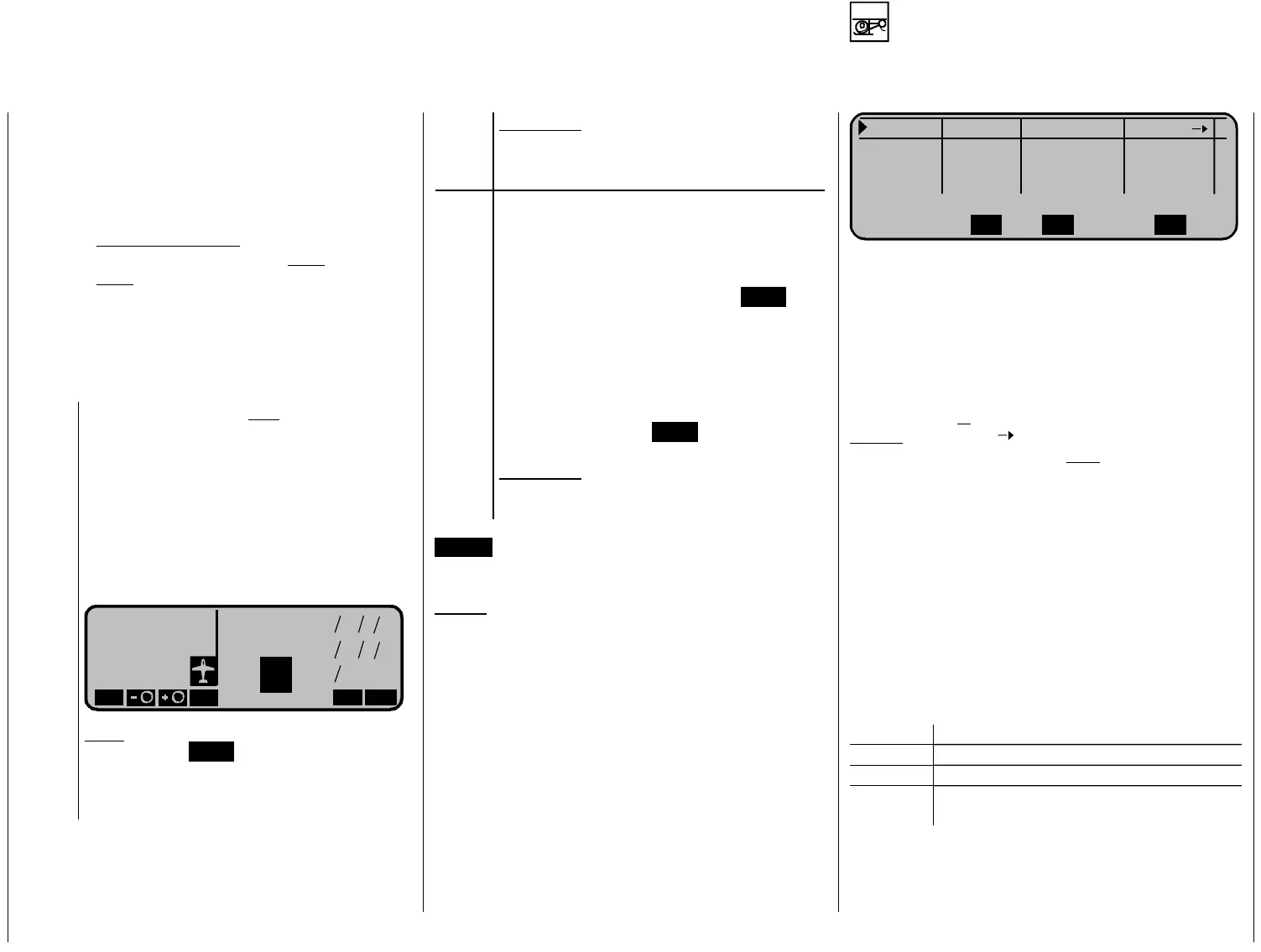
The next step is the new Code 52 »
Phase
assignment
« in which the neseccary “p
Autorot Autorot 0.0s -
Phase 1
Phase 2
0.0s
sch. Zeit
0.0s -
Phase 3 0.0s -
Name Flugph. Uhr Um
SELSEL SEL
e flight phas “Autorota
furt flight stm
s kno as “ ht
pha s“.
progra of flight phase s
ct has m
the p ch .
ng
Apart from th e tion“ you can
program a her 7 independant adju
ents
for variou
se
modes of flight normally wn Flig
You start the mming s in thi
menu. Sele
maybe a time
for the neseccary p
r and delay time for
es a na e and
hase ange
The switchi
to the autorotation phas alwa
wit
e is ys
hout. The arrow “ “ means that you an sw c itch
“softly“ into a different phase
from the pha
n“.
se
ste eces as
s n t
se a gnm «.
hase
ee
ches are
e
ents of
.
s displayed in the right column for
p to 7:
Sy ol D
“Autorotatio
In the next
wi es i
p you select the n sa hry p
s i
e
tch he new Code 52 »
Pha
You find the two switch function for the p
s ent
“Autorotation“ in Code 49 »
Auxiliary switch«, s
hand book mc-24/1, Page 63. When all swit
selected you can start with the programming in th
flight phase dependant menus for the adjustm
rs will be reset with
hase
switches“ are enabled (see page 25).
the individual flight phases – see table on page 22
Switch allocation i
hases 1
mb escription
- No switch planned
+ P ch h tase recall via swi
∗
Ma umber ater nkes the phase alloc d to
the switch position
 Loading...