Analyzer Installation & Connections
12
3.4 Electrical Connection
Each analyzer will be configured at the factory to be either:
• An Inert Gas Oxygen Analyzer for monitoring O2 in inert gas
• A Stack Gas Oxygen Analyzer for monitoring O2 in stack gas
• An EGR Oxygen Analyzer for monitoring O2 in the EGR system
For the default configuration and connection of each analyzer, check the Testing &
Configuration Sheet attached to each analyzer.
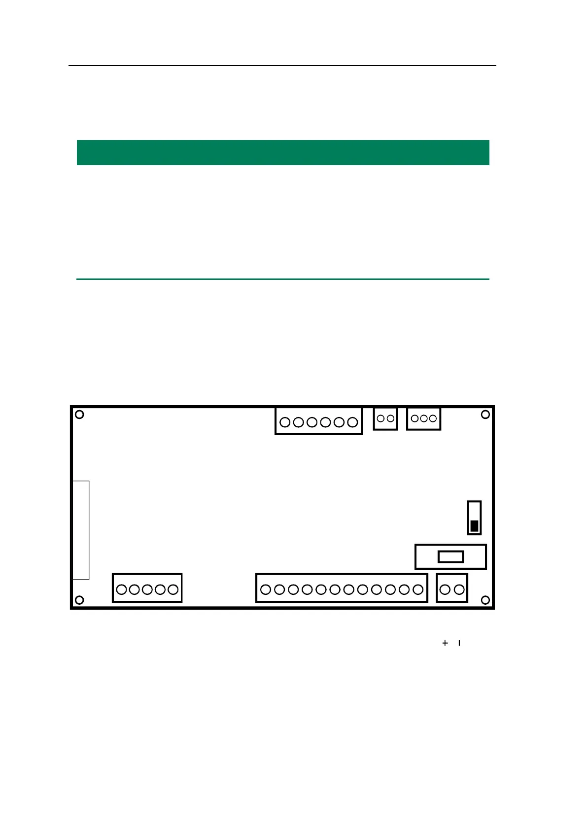
The electrical connections are dependent on the actual system configuration. The termi-
nals are all located on the back of the analyzer. For details, please see Figure 3-1. Only
those functions to be used shall be connected.
Please choose the cables that fulfill the following requirements:
Wire size for analog input and CAN connection: 1 x 1.0 mm2 w/screen
Wire size for all other connections: 1 x 1.5 mm2 w/screen
SD-CARD
CAN
4. A-OUT 2 +
5. A-OUT 2 –
1. A-OUT 1 +
2. A-OUT 1 –
3. NOT USED
A-OUT
6. GND
5. Oxygen he
at
4. NOT USED
3. Oxygen
2. Oxygen
1. Oxygen
1. A-IN 1 +
2. A-IN 1 –
24 V DC
8.3 COM
1.1 NC
2.1 COM
3.1 NO
4.2 NC
5.2 COM
6.2 NO
7.3 NC
9.3 NO
10.4 NC
11.4 COM
12.4 NO
D-OUT
SEN
A – IN
ON OFF
2AT –
Fuse
5x20
FUSE
Figure 3-1: The G36p connection terminals