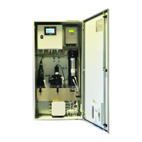
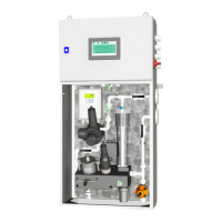
G36p
Oxygen Analyzer
Version 2.11 – Revision March 2022 13
3.4.1 Power Supply
The power supply terminal is located at the bottom right corner and is marked supply rat-
ing (24 VDC). For details please see figure 3-1. Before connecting the power supply,
please make sure that the power supply rating of the analyzer corresponds with the power
supply available.
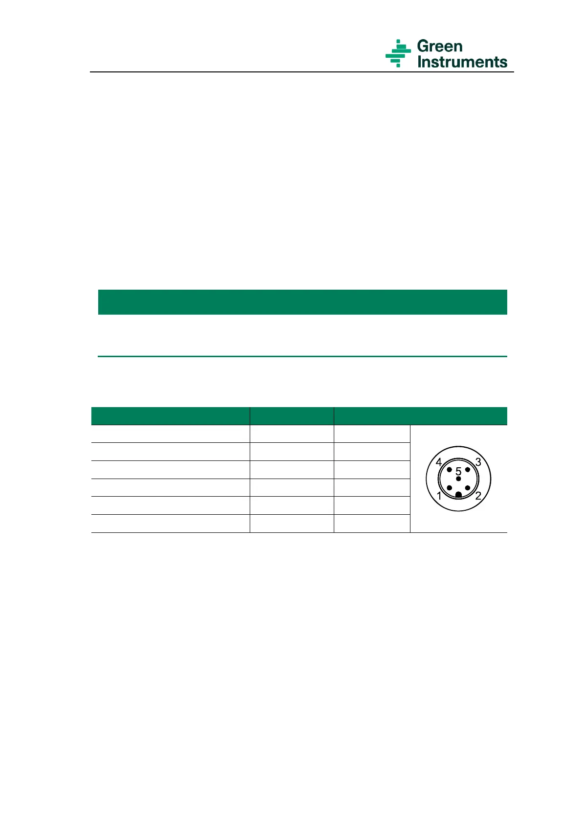
3.4.2 Sensor Connections – SEN
The analyzer is equipped with either a SEN1 or a SEN9 sensor (see the Testing & Con-
figuration Sheet). The sensor is connected to the terminal SEN in the analyzer.
Each analyzer is delivered with cable connections that are fit for use for either
SEN1 or SEN9. See chapter 9 for the spare parts.
The sensors are connected to the terminal SEN as follows:
Pins at SEN9’s connection
Terminal 1 (Sensor electrode)
Terminal 2 (Sensor electrode)
Terminal 3 (Sensor electrode)
Terminal 4 (No connection)
Terminal 5 (Sensor heating)
The cable between sensor and the analyzer can be delivered up to 6 m in length.
3.4.3 Relay Outputs – D-OUT
The analyzer is arranged with four relay outputs connected to D-OUT with 12 terminals.
It is important to note that the configuration of the analyzer might deviate from the con-
figurations listed below. Please see the Testing & Configuration Sheet that is attached to
each analyzer.
The default relay functions, and connections of the Inert Gas Oxygen Analyzer are as fol-
lows: