Greenlee Textron / Subsidiary of Textron Inc.
11
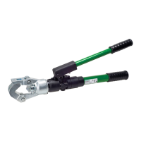
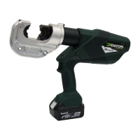
1990 Dieless Hydraulic Crimping Tool
Cylinder Cap — Serial Code WH
1. Unscrew the driving rod (94) from the stepped rod
(84).
2. Remove four cap screws and copper washers
(59, 60). Remove the cylinder cap (42).
3. Inspect various components (43–45, 54, 55).
Replace if worn or damaged.
4. Remove the check ball bushing (58), ball (53) and
spring (57). Inspect the O-ring (56).
Cylinder Cap — Serial Code YM
1. Unscrew the driving rod (94) from the stepped rod
(84).
Note: To service the check valves (49, 58) only,
proceed to Step 4.
2. Remove four cap screws and copper washers
(59, 60). Remove the cylinder cap (42).
Note: The cylinder cap must come straight off.
3. Inspect various components (43, 44, 54, 55).
Replace if worn or damaged.
4. Remove the check ball sleeve (58), ball (53), spring
(57), O-rings (29, 56) and backup ring (32).
Reservoir
1. Reposition the tool in the vise so that the handles
are upward. Retract the ram by pulling the release
trigger back while pressing down the handle.
2. Peel out the RTV (16) and remove the set screw
(17) from the reservoir handle (18).
3. Unscrew the reservoir handle from the pump block
(46).
4. Remove the plug (19) from the reservoir (20).
5. Remove the tool from the vise and pour the oil into
a waste oil container.
6. Remove O-ring (21) and reservoir (20) from the
pump block.
Pump Block, Relief Valves, and
Pressure Release Mechanism
1. Serial Code WH: Remove RTV (101), screw (100)
and nylon washer (99). Turn set screw (93) clock-
wise until it is flush with the relief valve cap (87).
2. Remove the two machine screws (91) and relief
valve cover (90).
3. Slide out the relief valve cap (87) and remove the
following parts: stepped rod (84), roller guide (83),
adjusting roller (88), two slides (89), valve spring
cap (86), valve spring (85) and relief valve plunger
(81).
4. Use a spanner wrench to remove the pressure-
adjusting valve body (80) and copper washer (82).
5. Disassemble the low pressure relief.
Serial Code WH: Remove the jam screw, spring,
and ball (79, 78, 77).
Serial Code YM: Remove RTV, plug, spring, and
ball (101, 79, 78, 77).
6. Remove one retaining ring (15) and pin (14) from
handle (5). Remove handle assembly.
7. Unscrew the pressure release body (72). Remove
the ball (74) and spring (73). Remove the shaft (70)
from the body (72). Inspect the O-rings (69, 71) and
replace if worn or damaged.
Serial Code YM: Also remove copper washer (30).
8. Use a T-handle Allen wrench or similar tool to push
the check ball insert (49) out.
• Remove ball and spring (47, 48) from the pump
block (46).
• Serial Code WH: Remove roll pin and ball
(52, 51) from the insert (49).
• Serial Code YM: Remove roll pin and ball (52, 51)
from the body (49).
• Inspect the O-ring (50).
Pump Piston
1. Remove one retaining ring (15) and pin (14) from
handle (5). Remove handle assembly.
2. Remove cap screws (13) and pivot block (12).
3. Pull the low pressure plunger (66) upward and out
of the pump block. Check O-rings, quad ring (Serial
Code YM only) and backup rings (62–65), and
replace if worn or damaged.
4. Use an Allen wrench to unscrew the high-pressure
plunger (68).
5. Remove the copper washer (67).
6. Use a T-handle Allen wrench or similar tool to push
the check ball insert (49) out.
• Remove ball and spring (47, 48) from the pump
block (46).
• Remove roll pin and ball (52, 51) from the insert
(49).
• Inspect the O-rings (31, 50).
Disassembly (cont’d)