Greenlee Textron / Subsidiary of Textron Inc.
9
1990 Dieless Hydraulic Crimping Tool
Die Replacement
This procedure is divided into two sections — one for
the fixed die (which has some steps that are particular
to the serial code) and one for the movable die (which
includes both serial codes).
Fixed Die
1. Pull the pin (23). Remove one retaining ring (27),
pin (24) and fixed die assembly.
2. Serial Code WH: Note the positions and alignment
of the two outer die plates and two inner die plates.
Remove the jam nuts (29) and bolts (28). Remove
the die plates (30, 31).
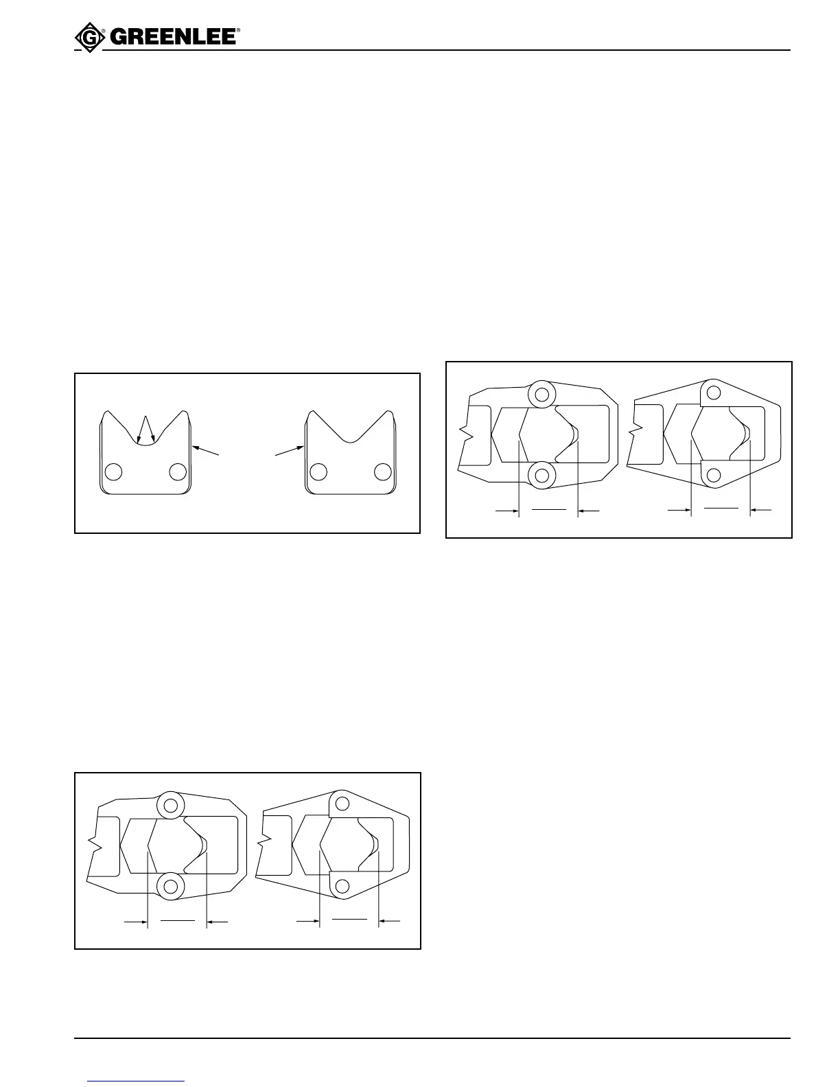
Install new die plates, ensuring that they are located
properly in the appropriate grooves, and that they
are in the proper sequence.
Outer Die Plate Inner Die Plate
Lower
Radii
Side with
grooves
faces out.
3. Serial Code YM: Transfer the ball detent (22) and
removable pin unit (23) to the new die head. Secure
with pin (24) and retaining ring (27).
4. Rotate the cylinder fully counterclockwise and fully
retract the ram. Measure the distance between the
outermost blades of the movable and fixed dies.
The distance should be between 56 and 57.1 mm
(2.205" and 2.250"). If the dimension is outside of
this range, remove the set screw (25) and movable
die (26) and change the number of spacers as
follows:
• to increase the distance, remove a spacer (102)
• to decrease the distance, add a spacer (102)
2.250"
2.205"
YM
2.250"
2.205"
WH
5. Install the movable die (26) and secure with the set
screw (25).
Movable Die — Either Serial Code
1. Remove the fixed die. See Step 1 under Fixed Die.
2. Remove set screw (25) and movable die (26).
3. Install new movable die and set screw.
4. Install fixed die.
5. Rotate the cylinder fully counterclockwise and fully
retract the ram. Measure the distance between the
outermost blades of the two dies. The distance
should be between 56 and 57.1 mm (2.205" and
2.250"). If the dimension is outside of this range,
remove the set screw (25) and movable die (26):
• to increase the distance, remove a spacer (102)
• to decrease the distance, add a spacer (102)
2.250"
2.205"
YM
2.250"
2.205"
WH
6. Install the movable die (26) and secure with the set
screw (25).