Greenlee Textron / Subsidiary of Textron Inc.
12
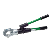
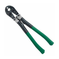
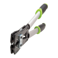
1990 Dieless Hydraulic Crimping Tool
1. Install backup ring (37) and O-ring (36) onto ram
(38).
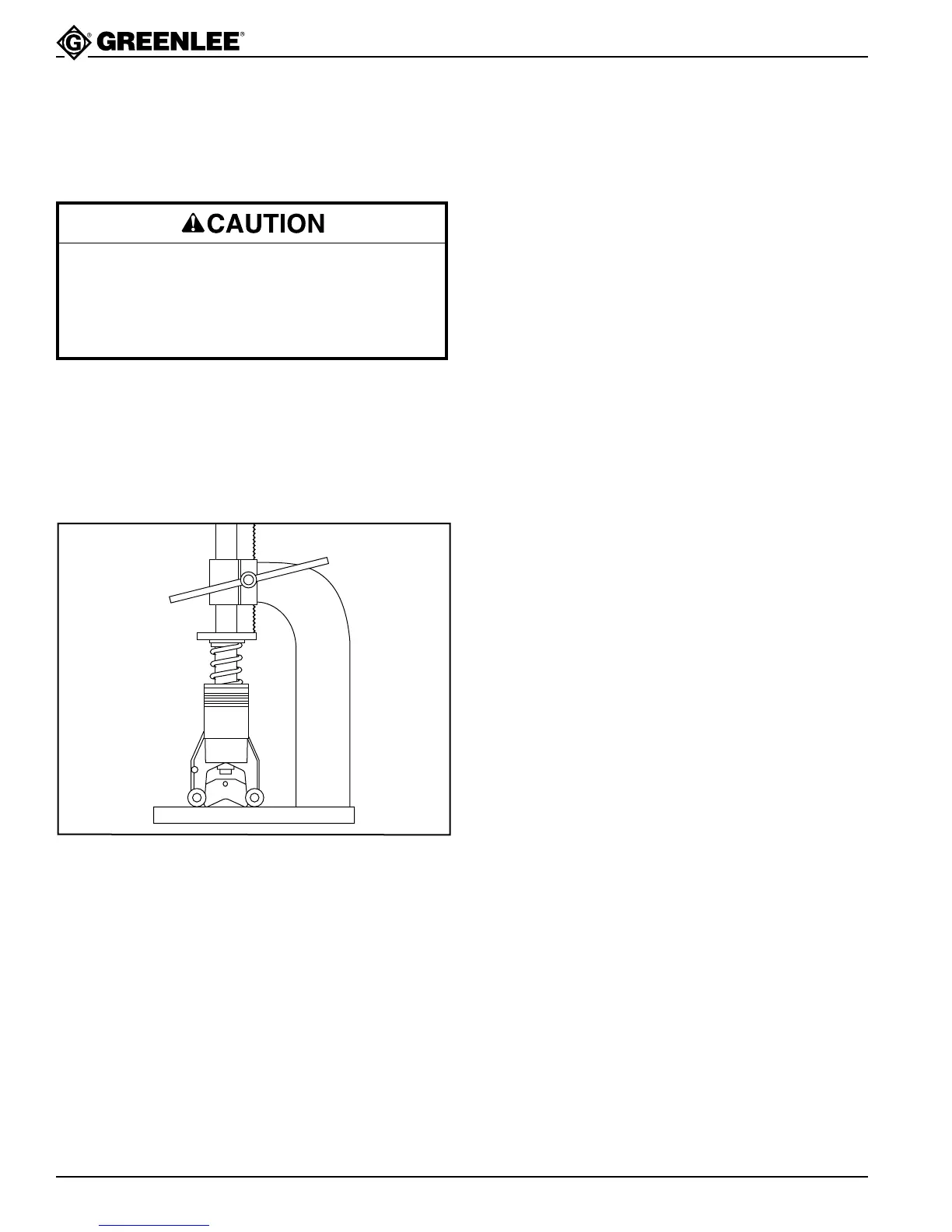
2. Clamp the cylinder (33) in a vise with the bore
upward. Install wiper and guide (34, 35).
3. Install spring (39) and ram assembly into cylinder
(33). Compress the spring using either an arbor
press or a C-clamp.
4. Slide the ram die (26) into place. Tighten set screw
(25) securely.
5. Set the assembly aside.
Cylinder Cap Assembly
1. Install the seal and backup washer (40, 41) into the
cylinder cap (42).
Serial Code WH: Install backup ring (43), O-ring
(44) and retaining ring (45) onto the cylinder cap.
2. Set the assembly aside.
Assembly
The spring stores at least 310 Newtons (70 pounds)
of force. Follow this procedure exactly as instructed
to contain the spring and its energy.
Failure to contain the spring will release all of its
energy, resulting in injury due to flying parts.
Pump Block Assembly — Serial Code WH
Perform this procedure with the pump block (46)
secured in the vise with the threaded end downward.
1. Assemble the check ball insert assembly (49) as
follows: Install O-ring (50), 3/16" diameter ball (51),
and roll pin (52). Set this assembly aside.
Note: Roll pin must be below the surface of the
check ball insert. A protruding roll pin will damage
the pump block.
2. Assemble 3/16" diameter ball (47) and spring
(48) — with small end toward ball — into the pump
block (46). Install check ball insert assembly (49)
into pump block. Insert 1/4" diameter ball (53) into
the check ball insert assembly. Seat each ball in its
hole.
3. Loosen jam screw (61). Assemble O-rings (54–56),
bushing (58) and spring (57) to cylinder cap. Torque
the bushing (58) to 4 Newton-meters (3 foot-pounds).
4. Set cylinder cap in place on the pump block and
install four copper washers (56) and cap screws
(59). Torque to 27 Newton-meters (20 foot-pounds).
5. Twist jam screw (61) clockwise until set.
Pump Block Assembly — Serial Code YM
Perform this procedure with the pump block (46)
secured in the vise with the threaded end downward.
1. Assemble the check ball insert assembly (49) as
follows: Install O-rings (50, 31), install and seat
3/16" diameter ball (51), and install roll pin (52). Set
this assembly aside.
2. Assemble 3/16" diameter ball (47) and spring
(48) — with small end toward ball — into the pump
block (46). Install check ball insert assembly (49) into
pump block. Insert 1/4" diameter ball (53) into the
check ball insert assembly. Seat each ball in its hole.
3. Assemble the sleeve (58) with O-rings (29, 56),
backup ring (32) and spring (57) to the pump block.
Torque the sleeve (58) to 4 Newton-meters
(3 foot-pounds).
4. Assemble the O-ring (44), backup ring (43) and
copper washers (54, 55) to the cylinder cap (42).
5. Set cylinder cap in place on the pump block and
install four copper washers (56) and cap screws
(59). Torque to 27 Newton-meters (20 foot-pounds).
Pump Plunger Assembly
1. Cut 6 mm (1/4") off of backup ring (62) to prevent
overlap. Assemble O-rings and backup rings
(63, 62, 65, 64) to the low-pressure plunger (66).
2. Assemble copper washer (67) and high-pressure
plunger (68) to the pump block. Torque to 24.5 to
27 Newton-meters (18 to 20 foot-pounds).
3. Install low-pressure plunger assembly onto the high-
pressure plunger assembly.
Note: Lubricate all O-rings and backup rings before
assembling.
Cylinder