Greenlee Textron / Subsidiary of Textron Inc.
15
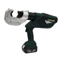
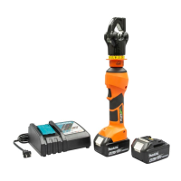
1990 Dieless Hydraulic Crimping Tool
Service Tips
• If the hydraulic system has air in it, purge the air and
top off the oil as instructed under Air Purging and Oil
Filling procedure. See Air in the Hydraulic System
at the end of the troubleshooting table.
• Check valve service requires removal of the cylinder
and cylinder cap. Inspect the ball seats in the pump
block and check body.
• If performing release mechanism service, check for
clearance between the ball (74) and release pin (70).
Inspect the body seat, body seats at the bottom of the
hole, and (Serial Code WH) against the block or
(Serial Code YM) against the copper washer (30).
• Low pressure relief service:
Serial Code WH: Drain and remove reservoir (20).
Remove relief cap (87) to allow access to the spring
retaining screw. Remove screw (79), spring (78) and
ball (77). Inspect parts for contaminants and seat for
damage. Clean and repair.
Serial Code YM: Remove RTV (101), O-ring plug
(79), spring (78) and ball (77).
• High pressure relief service: Drain and remove
reservoir (20). Remove relief cap (87) to allow access
to the relief valve and control mechanism. Remove
slides (89), roller (88), spring cap (86) and spring (85).
Remove cone (81). Check torque on the adjusting
body. Reseat cone, clean and assemble.
• Pump piston O-rings: Remove retaining rings (15)
from pins (14) and remove handle unit from pump
block (46). Remove the two cap screws (13) and pivot
block (12). Pull the low pressure plunger (66) upward
and out of the pump block. Check O-rings and backup
rings (62–65), and replace if worn or damaged.
• The pump handle can be disassembled by removing
the front pin and pivoting the handle up and beyond
the normal stroke.
Assembly (cont’d)
Final Assembly
1. Rotate the cylinder counterclockwise until it stops.
Fully retract the ram.
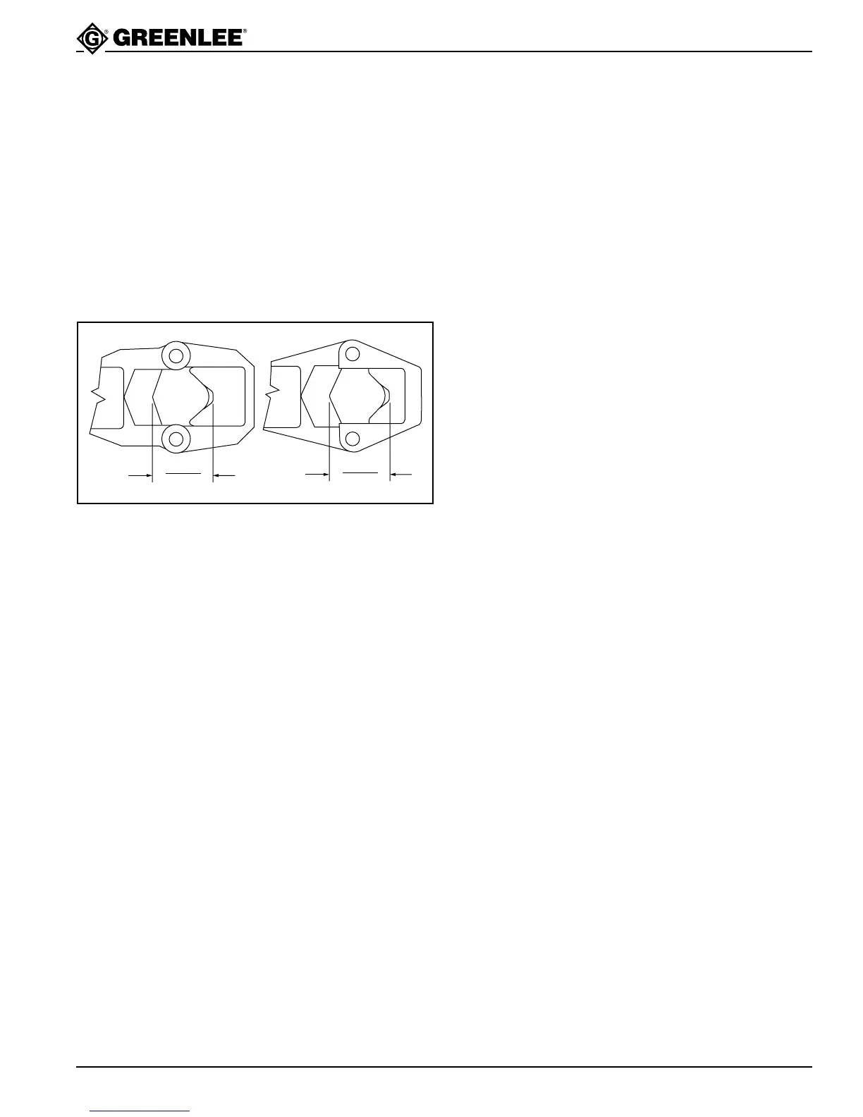
2. Measure the distance between the outermost
blades of the movable and fixed dies. The distance
should be between 56 and 57.1 mm (2.205" and
2.250"). If the dimension is outside of this range,
remove the set screw (25) and movable die (26)
and change the number of spacers as follows:
• to increase the distance, remove a spacer (102)
• to decrease the distance, add a spacer (102)
2.250"
2.205"
YM
2.250"
2.205"
WH
3. Install the movable die (26) and secure with the set
screw (25).
4. With the tool still in the vise, pour some hydraulic oil
into the pump block. Pump the handle until the ram
is fully extended.
Note: When the ram is fully extended, the handle
resistance will increase and some oil will squirt
back.
5. Install reservoir (20) and O-ring (21). Retract the
ram and purge air from the tool. Add oil until reser-
voir overflows. Wipe off the excess oil.
6. Proceed to calibrate the tool. See the Pressure
Adjustment Procedure.