Greenlee Textron / Subsidiary of Textron Inc.
14
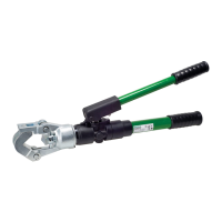
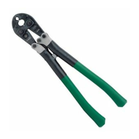
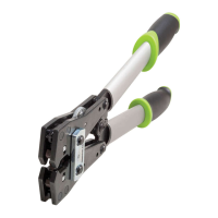
1990 Dieless Hydraulic Crimping Tool
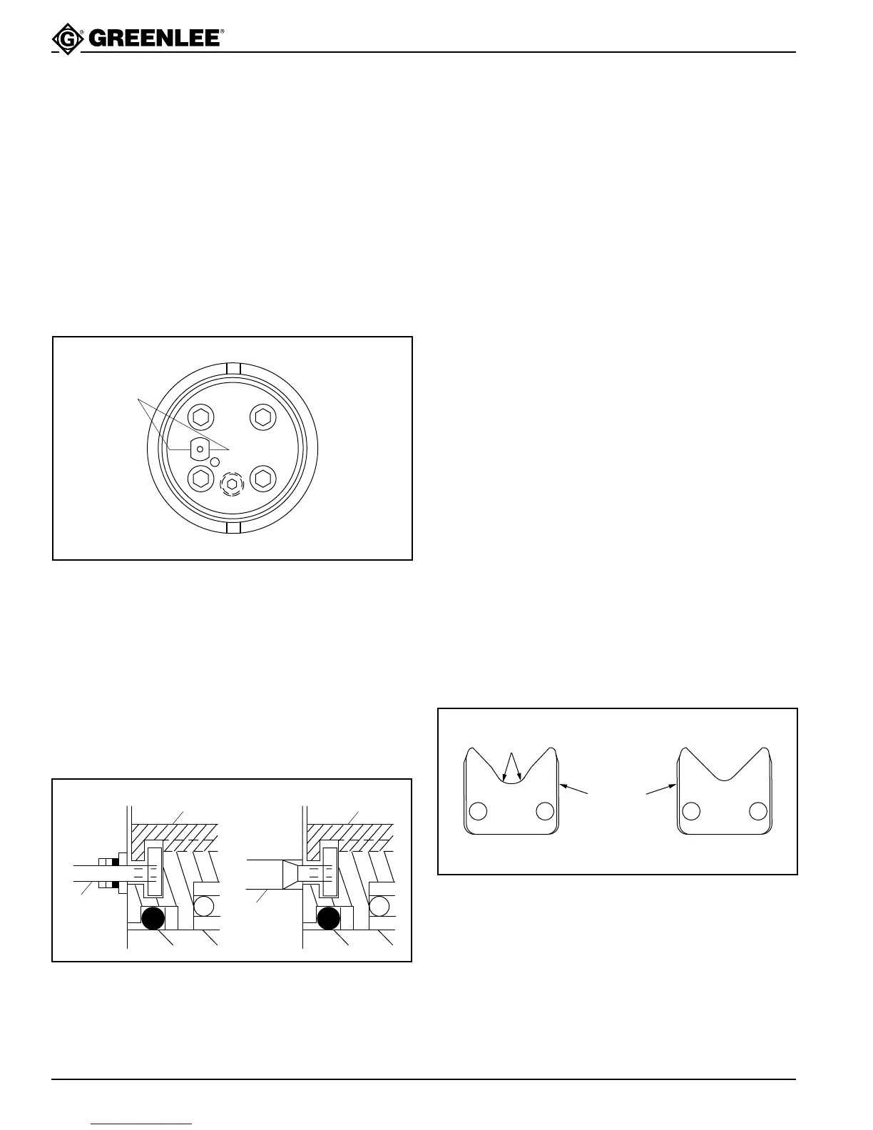
Assembly of Cylinder to Cylinder Cap
1. Push the stepped rod (84) out until the adjustment
roller (88) drops into the notch in the guide roller
(88), which will produce an audible “click”.
2. Apply a threadlocking compound, such as Loctite
®
222 Threadlocker or equivalent, to the threads of
the driving rod (94). Screw the driving rod into the
roller guide (83) until the driving rod just bottoms on
the cylinder cap. This setting is critical to the
proper operation of the tool.
Hint: For ease of assembly, screw the driving rod
clockwise until the flats are aligned as shown.
Flat Sides
of 94
3. Pull the driving rod out 38 mm (1-1/2").
Note: Pulling the rod out too far will cause the roller
(88) to fall off of the stepped rod. If this happens,
disassemble and start over at Step 1.
4. Hook the head of the driving rod (94) into the
groove of the ram (38).
5. Apply a threadlocking compound, such as Loctite®
222 Threadlocker or equivalent, to the threads of
the rod retaining screw (95). Screw the retaining rod
in until it is 0.81 mm (.032") below the back surface
of the ram.
YMWH
95
94
95
94
6. Screw the cylinder assembly (33) into the cylinder
cap until it is fully bottomed. Back the cylinder out to
allow installation of the set screw (96), as follows:
• Do not back the cylinder out more than 180°.
• There are two tapped holes for the set screw.
Install the set screw in either hole.
• Adjust the set screw (in or out) until the head
rotates 180° freely.
• Do not tighten the set screw.
Pump Handle Assembly
1. Assemble release trigger (2) to pressure release rod
(3) with roll pin (4). Insert into handle (5) and fasten
with roll pin (7).
Serial Code WH: Install trigger stop roll pin (6).
2. Assemble the pressure release bar (8) and torsion
spring (9) to the handle with roll pins (10). Glue grip
(11) to handle (5).
3. Mount the lever pivot block (12) to the pump block.
Fasten with two cap screws (13). Torque to
20 Newton-meters (15 foot-pounds).
4. Install the pump handle as follows:
Serial Code WH: Secure the handle to the lever pivot
block (12) and low pressure plunger (66) with two pins
(14). Secure the pins with retaining rings (15).
Serial Code YM: One pin is permanently mounted
in the handle. Install the handle so this pin engages
the low-pressure plunger (66). Then fasten the
handle to the lever pivot block (12) with the pin (14).
Secure the pin with retaining rings (15).
5. Serial Code WH: Assemble the fixed die head. See
the following illustration and the exploded view.
Outer Die Plate Inner Die Plate
Lower
Radii
Side with
grooves
faces out.
Install the bolts (28) and nuts (29). Torque to
13.5 Newton-meters (10 foot-pounds).
6. Serial Code YM: Assemble the detent (22) to the
die head (28).
7. Install the spacer(s) (102) and movable die (26).
Secure by tightening set screw (25).
8. Fasten the fixed die to cylinder with pins (23, 24).
Secure pin (24) with retaining rings (27).
Assembly (cont’d)