QUICK BENCHTEST:
ConnectSensortothe T.DUCER terminalsasshownbelow,thenapplyPower.Whenproperlyconnected
asoftclickingcanbeheardfromthesensorandfigureswillshowonthelargeLCDdisplay.Test
operationoftheSLT32byholdingthesensorsteadilyandaimingataflat,stabletarget12to28"(305to
711mm)awayfromtheendofthesensor.AllowafewsecondsfortheSLT32tolockontothetarget
beforedisplayingitsdistance.TheSLT32willnowdisplaydistanceinftorcm(factorycalibration).
NOTE:TheSLT32willnotdetecttargetsbeyonduserentered MaxRg.
CONNECTIONS:POWERINPUT:
ThestandardmodelrequiresACpowerinputbetween100-130VAC50/60Hz(2ampfuseis
recommended).Noadjustmentsarenecessaryforanyvoltageinthisrange.Optional230VACrequires
powerinputbetween200-260VAC50/60Hz.(SeeOPTIONSsectionofthismanualforconnectionof
optional12VDCor24VDCpowerinput).
IMPORTANTNOTE:TocomplywithCSA/NRTLstandards,ACpowerinputandrelayconnection
wiresmusthaveconduitentrytotheinstrumentenclosure.
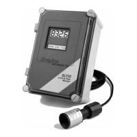
SLT32Level&FlowMonitor
ManualSeriesB.11
Page 4
T.DUCER
N.O
C
N.C N.O
C
N.C
N.O
C
N.C
RELAY 1
RELAY 2
RELAY 3
L
N
G
AC
RX
PU
GND
TX
RS 232
N.O
C
N.C N.O
C
N.C
N.O
C
N.C
RELAY 4
RELAY 5
RELAY 6
4\20
GROUNDSTUD
:
ATTACHCABLE
SHIELDS (4-20mA, RS232)
THIS ENDONLY
IMPORTANT
IMPORTANT:
MUST CONNECT TO A
GOODGROUND (<1 Ohm)
WITH12 AWG CONDUCTOR
OPTIONAL
100-130VAC(50/60 Hz)
OPTIONAL:
200-260VAC(50/60 Hz)
*
*
ALUMINUM CHASSIS