GRISWOLD PUMP COMPANY Repair Maintenance Page 29
Installation, Operation and Maintenance Manual
Griswold Model 811
Griswold Pump Company Repair Maintenance Page 31
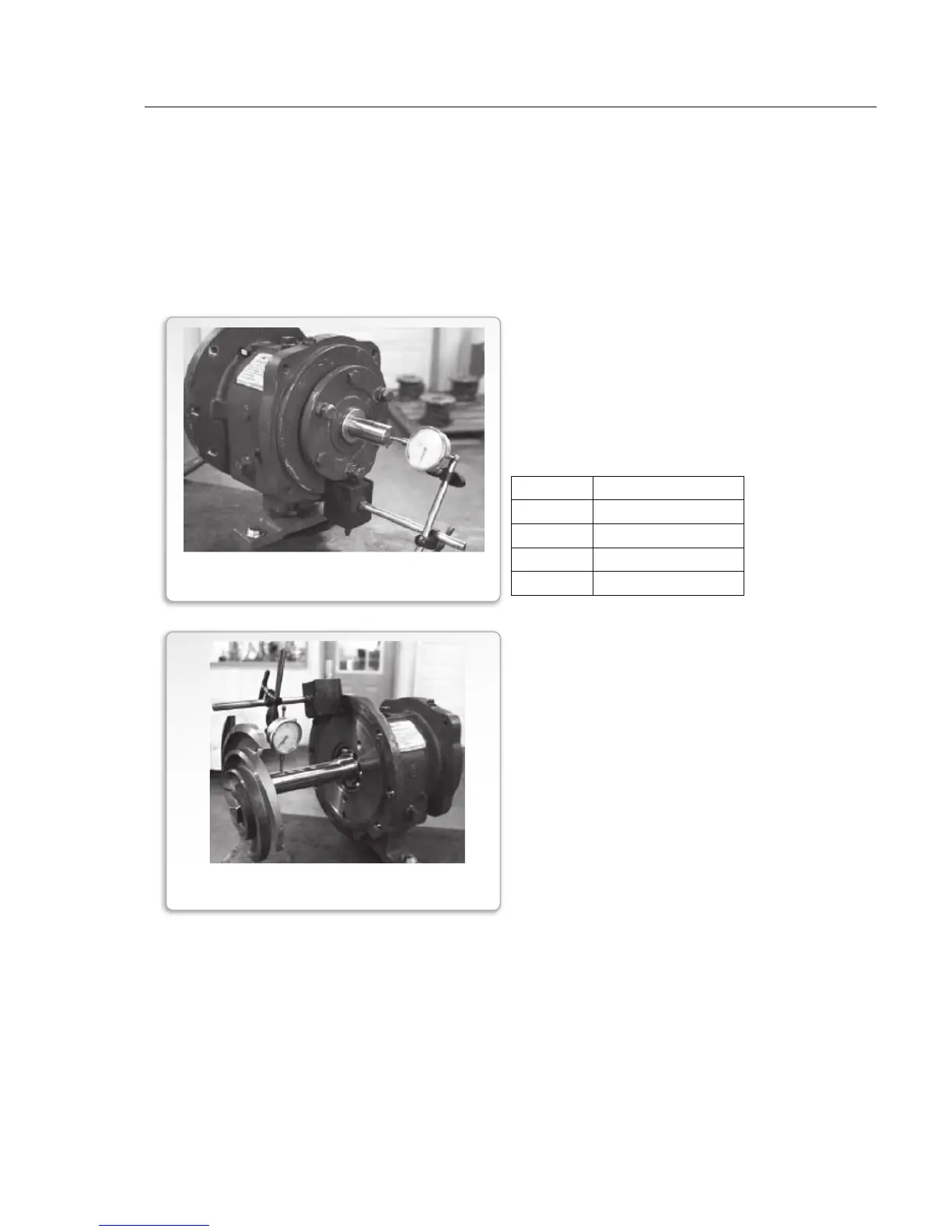
1. Install shaft sleeve (Item 126).
Install impeller (Item 101) on shaft
(Item 122).
2. Position dial indicator as shown at
left.
3. Rotate shaft one full revolution and
check for shaft/sleeve run out.
4. If total indicator reading (TIR) is
greater than 0.002", disassemble and
determine cause – correct.
6. Install new bearing housing o-ring (Item 496).
7. Lightly lubricate outside of bearing housing and ID of bearing frame bore. Install shaft
and bearing assembly into frame. Check that shaft rotates freely.
8. Install cap screws (Item 370C) into bearing frame (Item 228). Install jack bolts (Item
370D) and lock nuts (Item 423). Hand tighten evenly.
9. Replace frame foot (Item 241) and hand tighten bolts (Item 370F).
Power Frame Checks for Liquid End Assembly
Check Shaft Endplay
Place the power frame in the horizontal
position. Support frame assembly so that it
does not tip over. Check shaft endplay by
moving shaft forward and backward by hand.
Dial indicator movement should be within
tolerances below:.
Frame Endplay, inches
S 0.0011 – 0.0019
M 0.0013 – 0.0021
L 0.0010 – 0.0015
XL 0.0014 – 0.0023
FIGURE 21
SHAFT RUNOUT CHECK
FIGURE 20
BEARING END PLAY CHECK