GRISWOLD PUMP COMPANY Repair Maintenance Page 30
Installation, Operation and Maintenance Manual
Griswold Model 811
Griswold Pump Company Repair Maintenance Page 32
Power Frame Checks for Liquid End Assembly
Check Adapter Face Runout
1. Install adapter gasket (360D) on frame face.
2. Install frame adapter (108) with bearing isolator
seal (333A, M frame only) onto the power end
assembly. Make sure shouldered fit of adapter fits
inside of recess of the power frame. Align bolt
holes and dowel pin holes. Install dowel pins
(469B) and frame-to-adapter bolts (370B). Tighten
evenly in a crisscross manner.
3. Attach dial indicator to shaft. Place indicator
against mating face of adapter. Rotate shaft 360
degrees. Total indicator runout should not exceed
0.005. With dial indicator still attached to shaft,
position indicator on inside diameter of mating
face. Rotate shaft again a full 360 degrees. Total
indicator runout should not exceed 0.005 inch. If
greater values are measured, disassemble and
determine cause before proceeding with assembly.
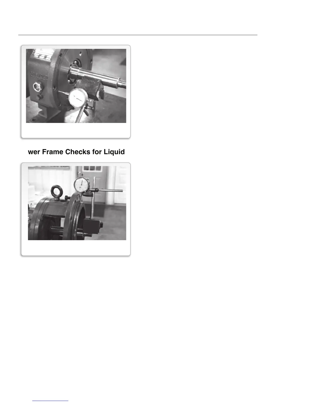
1. Attach dial indicator to shaft.
2. Place indicator against face of frame as
shown at left.
3. Rotate shaft by hand so that indicator
sweeps the entire fit for 360 degrees.
Maximum indicator runout should be
no more than 0.005 inch. If greater,
disassemble and determine cause.
FIGURE 22
FRAME FACE RUNOUT CHECK
FIGURE 23
ADAPTER FACE RUNOUT CHECK