GRISWOLD PUMP COMPANY Repair Maintenance Page 31
Installation, Operation and Maintenance Manual
Griswold Model 811
Griswold Pump Company Repair Maintenance Page 33
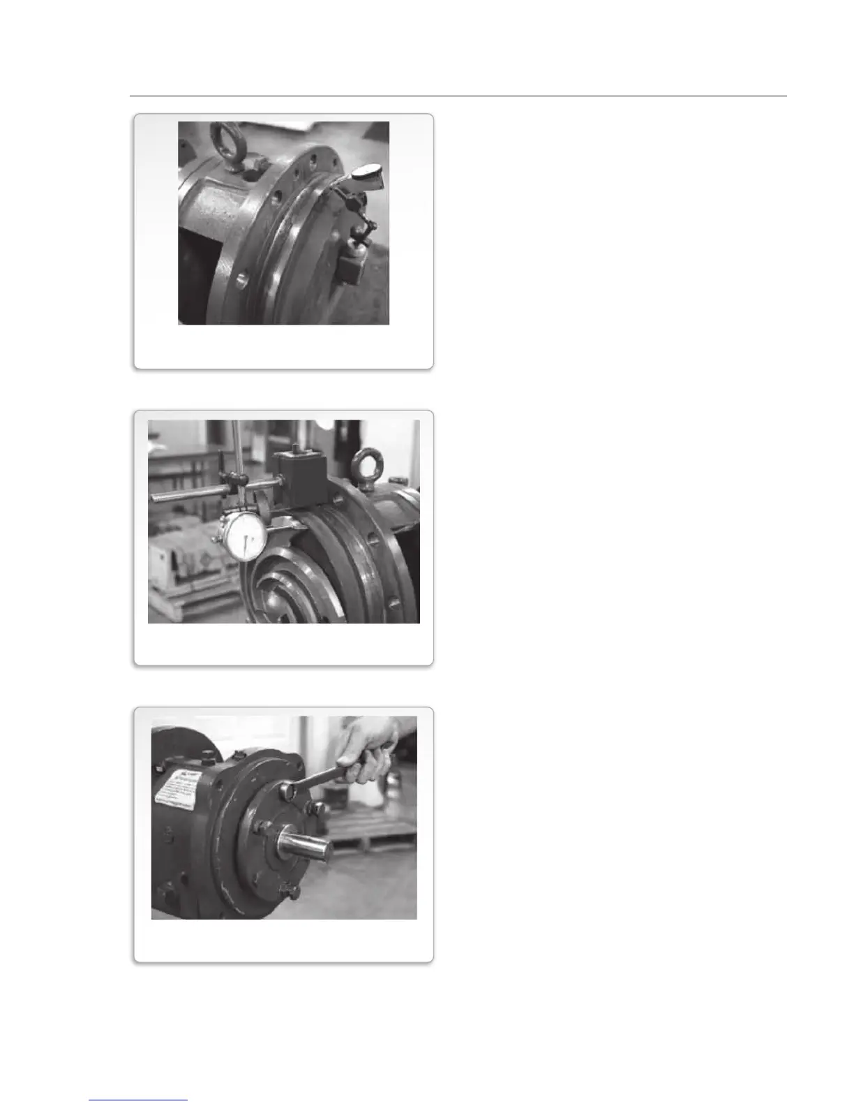
Check Stuffing Box Cover Runout
1. Install stuffing box cover (Item
184) with studs and nuts (Items
370H, 423B).
2. Mount dial indicator as shown.
Rotate shaft 360
O
indicator runout should not
exceed 0.005" for outside
diameter of pilot fit, face of
casing gasket surface and stuffing
box cover face.
If greater values are measured,
disassemble and determine cause before
proceeding with assembly.
1. Install shaft sleeve (if used) and
impeller. Lightly tighten
impeller onto shaft.
2. Attach dial indicator to flange of
frame adapter. Position indicator
on tip of impeller vane. Rotate
shaft 360 degrees. Check
impell
er run out from vane tip to
vane tip. Total indicator runout
should be less than 0.005 inch.
If greater values are measured,
disassemble and determine cause be
proceeding with assembly.
Preliminary Impeller Adjustment
1. Loosen clamp bolts (370C) and jacking
bolts (370D). Adjust impeller travel such
that the gap between the impeller (101)
and the stuffing box cover (184) is 0.030".
2. When 0.030" gap is reached, tighten clamp
bolts, jacking bolts and locking nuts (423).
This approximates the impeller position for
final impeller clearance adjustment.
FIGURE 24
STUFFING BOX COVER RUNOUT CHECK
FIGURE 25
IMPELLER RUNOUT CHECK
FIGURE 26
PRELIMINARY IMPELLER ADJUSTMENT