GRISWOLD PUMP COMPANY Appendix Page 51
Installation, Operation and Maintenance Manual
Griswold Model 811
Griswold Pump Company Appendix Page 53
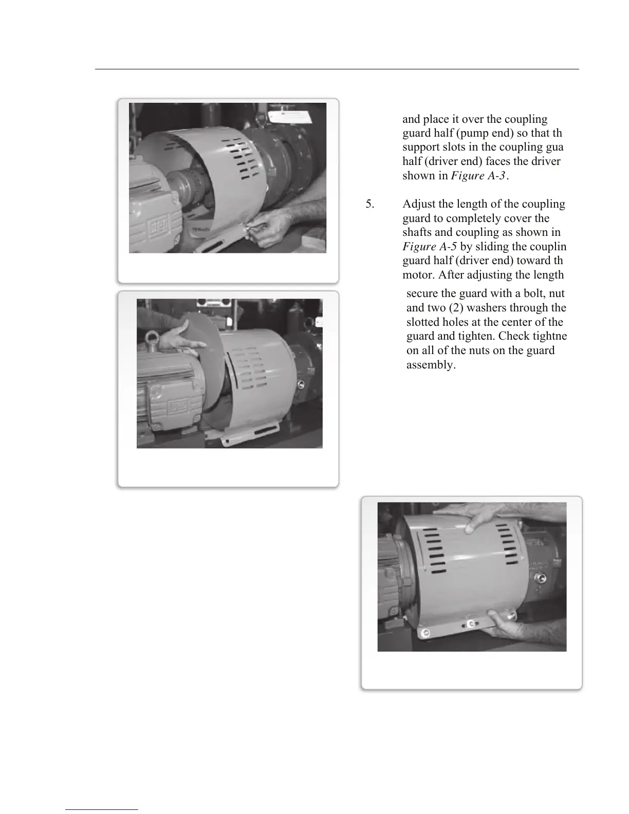
4. Slightly spread the bottom of
coupling guard half (driver end)
and place it over the coupling
guard half (pump end) so that the
support slots in the coupling guard
half (driver end) faces the driver as
shown in Figure A-3.
5. Adjust the length of the coupling
guard to completely cover the
shafts and coupling as shown in
Figure A-5 by sliding the coupling
guard half (driver end) toward the
motor. After adjusting the length,
secure the guard with a bolt, nut
and two (2) washers through the
slotted holes at the center of the
guard and tighten. Check tightness
on all of the nuts on the guard
assembly.
FIGURE A-5
COUPLING GUARD
ADJUSTING THE LENGTH
FIGURE A-4
COUPLING GUARD BARREL
DRIVER END
FIGURE A-3
COUPLING GUARD BARREL