-16-
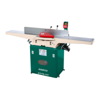
Model G0725 (Mfd. Since 03/18)
1. DISCONNECT JOINTER FROM POWER!
2. Use (2) M8-1.25 x 20 cap screws and (2)
8mm lock washers to attach the fence sup-
port to the jointer bed (see Figure 9).
Figure 9. Attaching the fence support to the bed
assembly.
Fence
Support
Jointer Bed
Cap Screws
3. Insert the locking plate assembly into the
fence support, positioning it so the two pins
are against the bottom edge of the fence sup-
port, as shown in Figure 10.
Figure 10. Inserting the locking plate.
Locking
Plate Pins
Locking Plate
Assembly
4. Attach the fence sliding handle to the lock-
ing plate assembly. Secure the locking plate
in position by tightening the fence sliding
handle, as shown in Figure 11.
Installing Fence
Figure 12. Assembling the fence assembly.
Bracket
Assembly
Fence
Cap
Screws
Figure 11. Securing the locking plate assembly
with the fence sliding handle.
Fence Sliding
Handle
Locking Plate
Assembly
5. Use the (4) M8-1.25 x 20 and (4) 8mm lock
washers to attach the fence to the fence
bracket assembly, as shown in Figure 12.
x 2
x 4
 Loading...