Model T31739 (Mfd. Since 11/19)
-17-
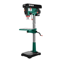
3. Suspend a plumb bob from center of
headstock spindle so it is over tape/ruler, as
shown in Figure 11.
4. Center headstock directly over base
as indicated by plumb bob and ruler
(see Figure 11).
Figure 11. Example of using plumb bob to align
headstock to base.
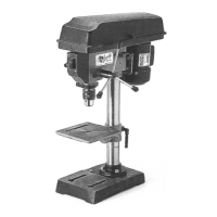
5. Tighten (2) pre-installed set screws to secure
headstock to column (see Figure 12).
Figure 12. Location of set screws that secure
headstock to column.
x 2
6.
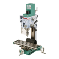
Attach table height crank handle to table arm
(see Figure 13) and secure by tightening
pre-installed set screw against worm shaft.
Figure 13. Table height crank handle attached to
table arm.
Table Arm
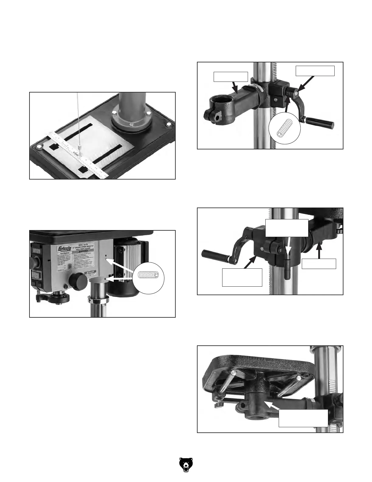
7. Thread (1) table height lock handle into worm
gear housing cartridge (see Figure 14) and
tighten until table arm will not move.
8.
Install table into table mounting arm (see
Figure 15).
Figure 14. Table height lock handle inserted into
cartridge.
Table Height
Lock Handle
Worm Gear
Housing
Figure 15. Table installed into table arm.
Table Mounting
Arm
Table Arm
Worm Shaft
 Loading...