-4-
Model T31739 (Mfd. Since 11/19)
Controls &
Components
To reduce your risk of
serious injury, read this
entire manual BEFORE
using machine.
Refer to the following figures and descriptions to
become familiar with the basic controls and com-
ponents of this machine. Understanding these
items and how they work will help you understand
the rest of the manual and minimize your risk of
injury when operating this machine.
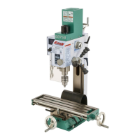
Table
Figure 2. Table controls.
Workpiece Support: Provides extra support for
long workpieces.
Table Height Crank Handle: Adjusts table height.
Table Pivot Lock Handle: Locks table to keep it
from rotating.
Workpiece Support Lock Knob (1 of 2): Locks
support arm in position.
Workpiece
Support
Table Pivot
Lock Handle
Table Height
Crank Handle
Workpiece
Support
Lock Knob
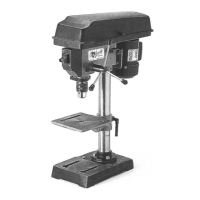
Control Panel
Figure 3. Control panel.
Emergency Stop Button: Immediately cuts
power to motor and control panel when pressed.
Twist button clockwise to reset.
ON/OFF Buttons: Turns drill press ON and OFF.
LED ON/OFF Switch: Turns work light ON or
OFF.
Digital Readout: Displays spindle RPM.
Laser ON/OFF Switch: Turns laser sights ON or
OFF.
Digital
Readout
Emergency
Stop Button
ON/OFF Buttons
LED ON/OFF
Switch
Laser
ON/OFF
Switch
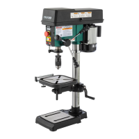
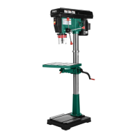
Headstock
Adjustable Depth Stop: Stops spindle travel at
predetermined depth.
Depth Scale: Indicates drilling depth and position
of depth stop.
Downfeed Handles: Moves spindle down when
pulled down. Spindle automatically returns to top
position when released.
Spindle Speed Lever: Adjusts spindle speed
rate from 400 to 2700 RPM.
Spindle Return Spring: Automatically returns
quill into headstock.
Quill: Houses spindle and spindle bearings.
Figure 1. Headstock controls.
Adjustable
Depth Stop
Depth Scale
Downfeed Handle
Spindle
Return Spring
Quill
Spindle Speed
Lever