English (GB)
13
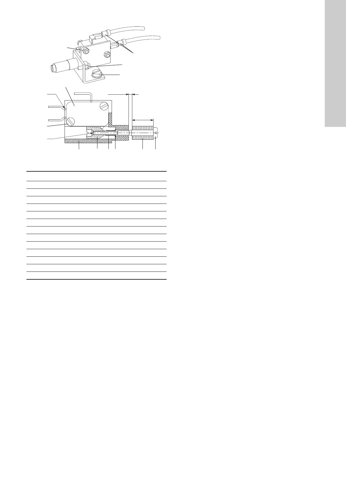
Fig. 11 Moisture switch
Checking the micro switch
1. Connect the switch to a simple bell circuit or similar test
circuit.
2. Pull the expander (5) two to three times to make sure that the
bell stops ringing when the expander is pulled outwards,
which breaks the electric circuit, and starts ringing when the
expander is free.
If the bell does not ring, turn the adjusting nut (3) outwards
until the bell rings.
Adjusting the clearance of the moisture switch
1. Connect the moisture switch in the test bell.
2. Place the feeler gauge between the mounting bracket (1) and
the expander (5).
3. Pull the expander (5) outwards.
If the bell rings turn the adjusting nut (3) clockwise until the
bell stops ringing.
4. Check the adjustment by removing the feeler gauge, reinstall
it and repeat step 2.
The test bell should connect on and off by gently moving the
feeler gauge.
5. Lock the adjusted moisture switch with Loctiet 290 thread
locking compound by adding a drop of it in the cavity of the
adjusting nut (3).
Replacing the moisture switch
1. Dismantle the pump, leaving only the stator housing.
See section 9.4 Dismantling.
2. Remove the sensor protector (plastic cover).
3. Remove the mounting screw (12) and lock washer (13) from
the mounting bracket (1).
4. Pull out the sensor from the stator housing (55).
5. Disconnect the spade connectors (11) from the switch.
6. Remove the screw (10).
7. Remove the switch from the mounting bracket (1).
Fitting a new moisture switch
1. Fit the moisture switch to the mounting bracket (1).
2. Fit the screw (10) to attach the switch to the mounting bracket
(1).
3. Fit the mounting bracket (1), including the switch on the stator
housing (55), with the mounting screw (12) and the lock
washer (13).
4. Connect the spade connectors (11).
5. Connect the wires according to the wiring diagram. See
section 12.5 Electrical data.
6. Fit the sensor protector (plastic cover).
7. Assemble the pump according to the instructions in section
9.5 Assembling.
TM06 9197 1917
Pos. Description
1 Mounting bracket
2 Shaft
3 Adjustment nut
4Spring
5 Expanding washer
6 Micro switch
7Screw
8Nut
9 Washer
10 Screw
11 Spade connectors
12 (186) Mounting screw
13 Lock washer
5
1
3
4
9
2
14 mm
L4 is to be cut.
7
8
6
Clearance: 5 ± 0.2 mm
10
11
12
13
Loctite 290-
thread locking
 Loading...