English (GB)
57
21. Installation of communication interface
module (CIM)
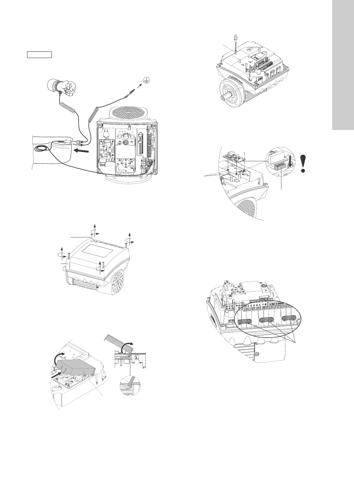
Fig. 79 Antistatic service kit
1. Disconnect the power supply to the pump.
2. Remove the terminal box cover by loosening the four screws
(fig. 80, A) and lifting the terminal box cover (fig. 80, B).
Fig. 80 Removing the terminal box cover
3. Remove the cover (fig. 81, A) by pressing the locking tab (fig.
81, B) and lifting the end of the cover (fig. 81, C). Then lift the
cover off the hooks (fig. 81, D).
Fig. 81 Removing the cover
4. Remove the screw (fig. 82, A).
Fig. 82 Removing the screw
5. Fit the module by aligning it with the three plastic holders (fig.
83, A) and the connecting plug (fig. 83, B). Press home the
module using your fingers.
Fig. 83 Align the module with plastic holders (A) and
connecting plug (B)
6. Fit and tighten the screw (fig. 82, A) with a torque of 1.3 Nm.
7. Make the electrical connections to the module as described in
the instructions delivered with the module.
8. Connect the cable screens of the bus cables to earth via one
of the earth clamps (fig. 84, A).
Fig. 84 Connecting cable screens to earth
Always use an antistatic service kit when handling
electronic components. This will prevent static
electricity from damaging components.
When unprotected, place the component on the
antistatic cloth.
TM06 4462 2315
TM06 4081 1515TM06 4084 1515
TM06 4082 1515TM06 4083 1515TM06 4195 1615
 Loading...