English (GB)
58
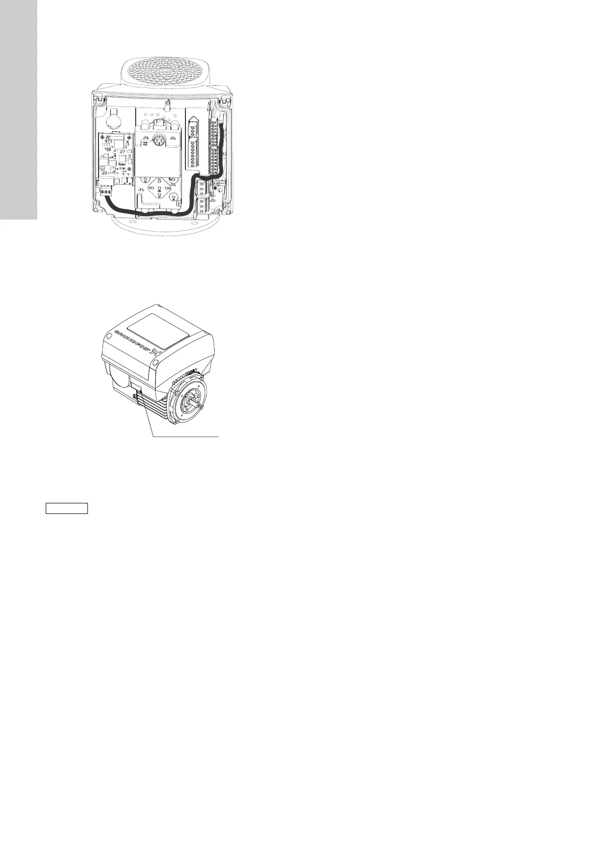
9. Route the wires for the module. See the example in fig. 85.
Fig. 85 Example of wire routing
10. Fit the cover.
11. If the module is supplied with an FCC label, then place this on
the terminal box. See fig. 86.
Fig. 86 Position of FCC label
12. Fit the terminal box cover (fig. 80, B) and cross-tighten the
four screws (fig. 80, A) to 6 Nm.
TM06 4085 1515TM05 7028 0413
Make sure that the terminal box cover is aligned with
the control panel. See section 16. Changing the
position of the control panel.
 Loading...