GSK218M CNC System Connection and PLC Manual
163
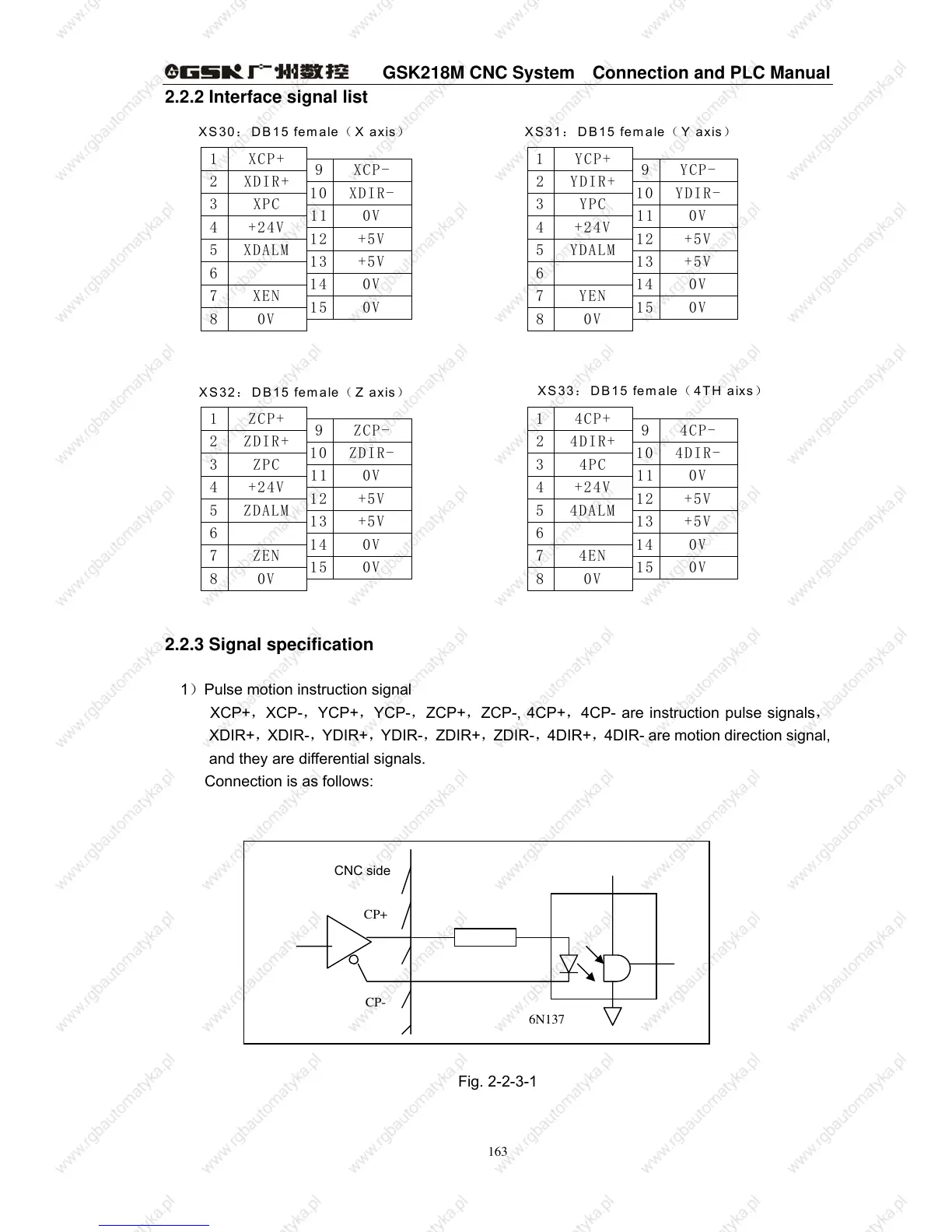
2.2.2 Interface signal list
6
ZDIR+2
6
8
7
0V
ZEN
4
5
3
+24V
ZDALM
ZPC
13 +5V
0V
0V
15
14
ZDIR-
0V
+5V
12
11
10
1 ZCP+
8
7
0V
XEN
ZCP-
9
0V
0V
15
14
XDIR+2
4
5
3
+24V
XDALM
XPC
1 XCP+
XDIR-10
+5V
+5V
0V
13
12
11
XCP-
9
6
4DIR+2
4EN
4DALM
4PC
+24V
6
8
7
4
5
3
+5V13
15
14
0V
0V
0V
12
11
10
+5V
4DIR-
0V
4CP+
YEN
1
8
7
9 4CP-
14
15
0V
0V
0V
YDALM
YPC
YDIR+
YCP+
+24V
2
4
5
3
1
YDIR-10
11
12
13
+5V
+5V
0V
9 YCP-
XS33: DB15 female( 4TH aixs)
XS32: DB15 female( Z axis)
XS31: DB15 female( Y axis)XS30: DB15 female( X axis)
2.2.3 Signal specification
1)Pulse motion instruction signal
XCP+,XCP-,YCP+,YCP-,ZCP+,ZCP-, 4CP+,4CP- are instruction pulse signals,
XDIR+,XDIR-,YDIR+,YDIR-,ZDIR+,ZDIR-,4DIR+,4DIR- are motion direction signal,
and they are differential signals.
Connection is as follows:
Fig. 2-2-3-1
CP+
CP-
6N137
CNC side