GSK218M CNC System Connection and PLC Manual
73
Note: When the mirror image is used and mirror image instruction is not executed(automatic
reference point return and manual operation), the mirror image check signal MMI1~MMI4 are
not influenced.
1.5 Position switch
General Position switch signals can be output to the PMC which the machine coordinates alogn
a controlled axes are within a specified ranges.
Signal position switch signal
PSW01-PSW05
<F014#0 ~ #4>
[Classfication] Output signal
[Function] Indicates that the machine coordinates along the controlled axes specified
by parameters. Up to 16 position switch signals can be output. (Using 11
or more position switches requires setting the ESP parameter. )
[Output conditions] The signals are 1 when:
The machine coordinate along the controlled axes are within the specified range.
These signals are 0 when:
The machine coordinate along the controlled axis are not within the specified range.
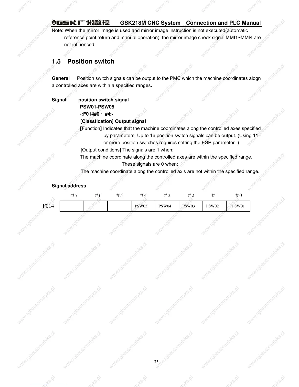
Signal address
PSW05 PSW04 PSW03 PSW02 PSW01
F014
#7 #6 #5 #4 #3 #2 #1 #0
 Loading...