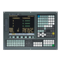
GSK218M CNC System Connection and PLC Manual
71
1.4 Mirror image
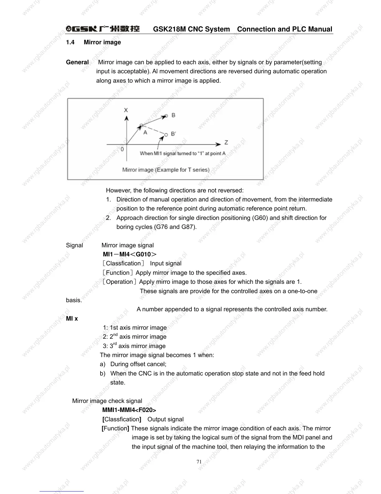
General Mirror image can be applied to each axis, either by signals or by parameter(setting
input is acceptable). Al movement directions are reversed during automatic operation
along axes to which a mirror image is applied.
However, the following directions are not reversed:
1. Direction of manual operation and direction of movement, from the intermediate
position to the reference point during automatic reference point return.
2. Approach direction for single direction positioning (G60) and shift direction for
boring cycles (G76 and G87).
Signal Mirror image signal
MI1-MI4<G010>
[Classfication] Input signal
[Function]Apply mirror image to the specified axes.
[Operation]Apply mirro image to those axes for which the signals are 1.
These signals are provide for the controlled axes on a one-to-one
basis.
A number appended to a signal represents the controlled axis number.
MI x
1: 1st axis mirror image
2: 2
nd
axis mirror image
3: 3
rd
axis mirror image
The mirror image signal becomes 1 when:
a) During offset cancel;
b) When the CNC is in the automatic operation stop state and not in the feed hold
state.
Mirror image check signal
MMI1-MMI4<F020>
[Classfication] Output signal
[Function] These signals indicate the mirror image condition of each axis. The mirror
image is set by taking the logical sum of the signal from the MDI panel and
the input signal of the machine tool, then relaying the information to the



 To Next Page