DA98A AC Servo Drive Unit
User Manual
54
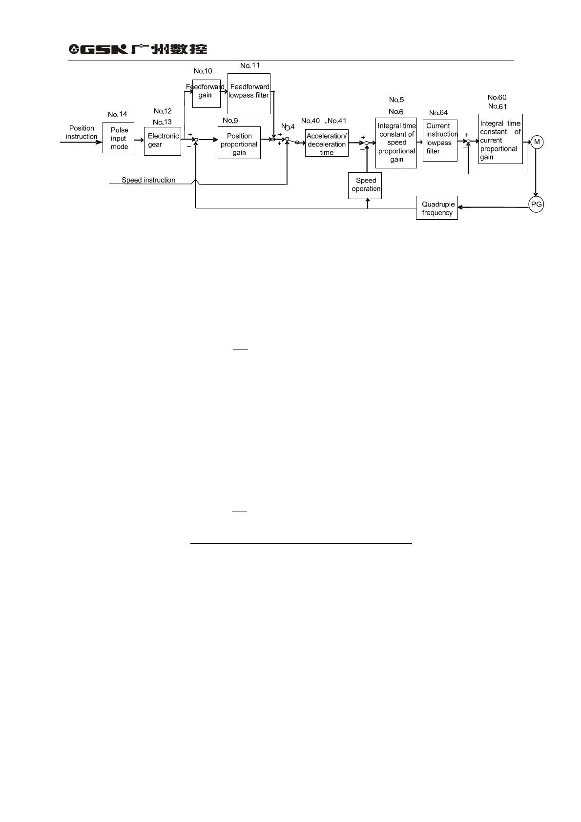
Fig. 7.4 Adjustment block diagram of primary parameters
3) Resolution and electronic gear setting
The position resolution (one pulse travel l) is defined by the travel S per rev of the servo △△
motor and feedback pulse P
t
per rev of encoder and their equation is as follows:
l=△
P
SΔ
l△ :travel per pulse(mm);
S△ :travel per rev of servo motor(mm/rev);
P
t
:feedback pluses per rev of encoder(pulse/rev).
Because there is quadruple frequency circuit in the system, P
t
=4×C and C is pulses per rev
of encoder. In this system, C=2500 pulses/rev and P
t
=10000 pulses/rev.
The instruction pulse multiplied by the electronic gear ratio G equals the position control
pulse, so one instruction pulse travel l* is expressed as follows:△
l*=△
P
SΔ
× G
And G=
divisionfrequency pulse ninstructio of Dominator
divisionfrequency pulse ninstructio of Numerator
4) ON-OFF adjustment
The on-off characteristic of servo system, i.e. acceleration and deceleration time, is
determined by the load inertia and on-off frequency and also restrained by the servo unit and
servo motor. Frequently on-off, too small acceleration and deceleration time and too large load
inertia may result in the overheating of servo drive unit and motor as well as the alarm for the main
circuit overvoltage, so it should be adjusted according to the actual situation.
(1) Load inertia and on-off frequency
In a high frequency situation, first make sure whether they are within the allowable frequency
range. The allowable frequency range varies with the motor type, capacity, load inertia and
motor speed. If the load inertia is m folds of the motor inertia, the allowable on-off frequency
and the recommended acceleration and deceleration time for the servo motor are as following
table: