DA98D User Manual
15
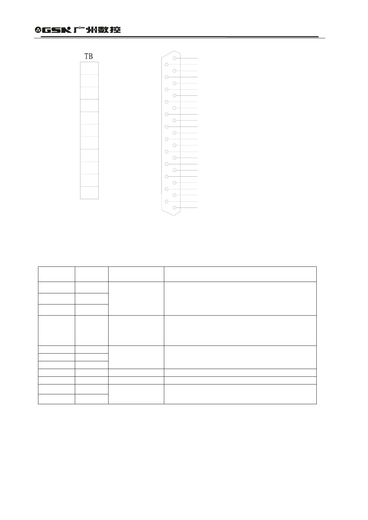
T
B
R
S
T
PE
U
V
W
P
D
r
t
13
25
12
24
11
23
10
22
9
21
8
20
7
19
6
18
5
17
4
16
3
15
2
14
1
MHP
NC
A-
A+
B-
B+
Z-
Z+
U-
U+
V-
V+
W-
W+
+5V
+5V
+5V
+5V
0V
0V
0V
FG
0V
FG
0V
CN2
DB25
Fig. 3.3 Configuration Chart for Interface Terminals of Servo Drive unit
2) Power Terminal TB
Table 3.1 Power Terminal TB
Terminal
No.
Terminal
Mark
Terminal Name Functions
TB-1 R
TB-2 S
TB-3 T
Major Loop
Power
Single-phase or
Three-phase
Input terminal of major return circuit power
~220V 50Hz
Notes: Do not connect with motor output terminals
of U, V and W.
TB-4 PE
Product
Earthling
Grounding terminals
Grounding resistance is less than 100Ω;
Servo motor output and power input have ground
contact at the common point.
TB-5 U
TB-6 V
TB-7 W
Servo Motor
Output
Servo motor output terminal; shall be connected
with motor terminals of U, V and W in the way of
one-to-one correspondence
TB-8 P Back up
TB-9 D Back up
TB-10 r
TB-11 T
Control Power
Single-Phase
Input terminal for control circuit power
~220V 50Hz
3) Control Terminal CN1
Simplified form of Control Modes:
P stands for position control mode
S stands for speed control mode