DA98D User Manual
19
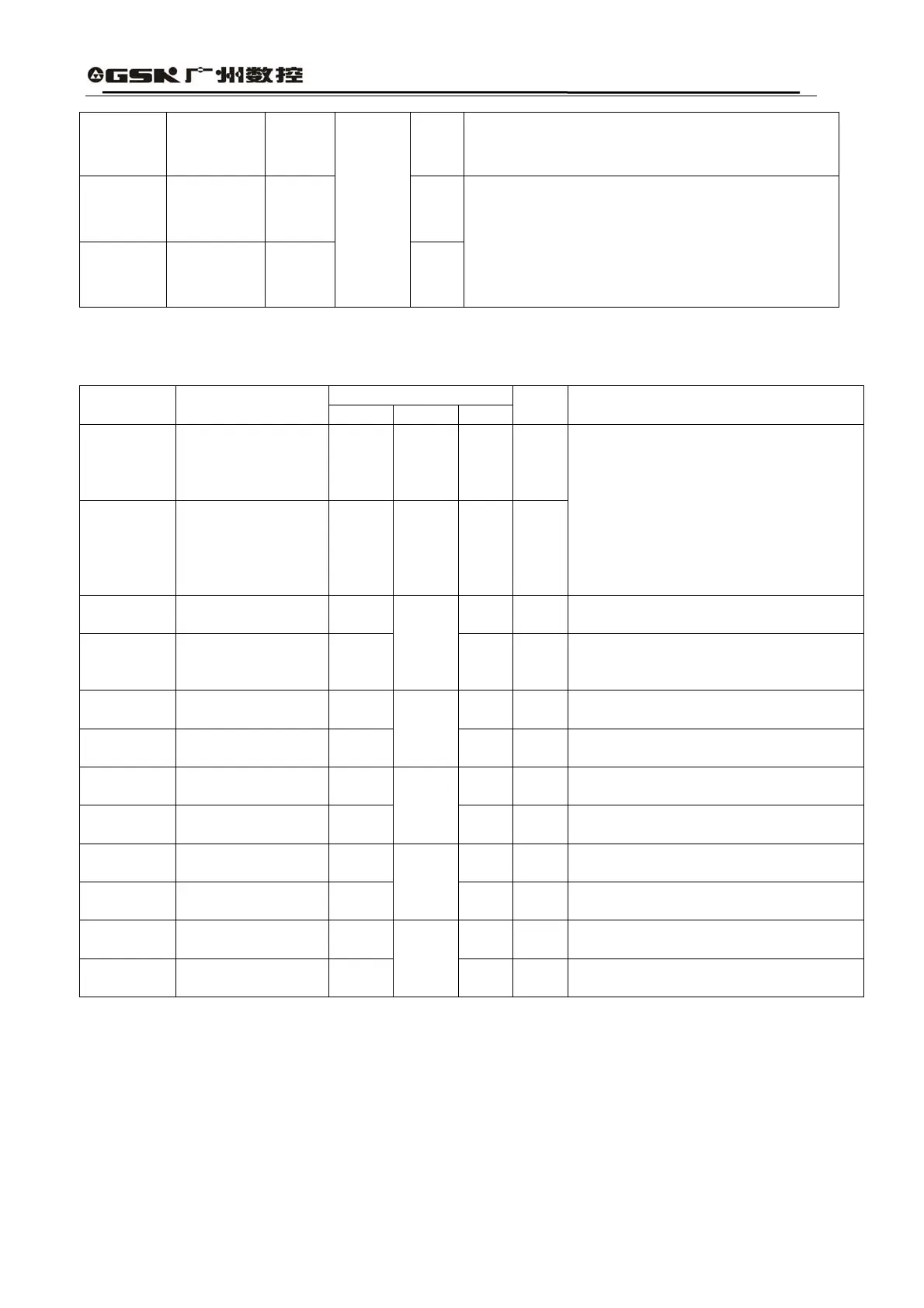
CN1-13
Code disc
Pulse B-
PBOUT-
CN1-42
Code disc
Pulse Z+
PZOUT
+
CN1-43
Code disc
Pulse Z-
PZOUT-
One pulse will be output from one round of the
motor.
Feedback Signal Terminal CN2
Table 3.3 Encoder Signal Input/Output Terminal CN2
Terminal Mark
Terminal
No.
Terminal Name
Mark I/O Mode
Color Functions
CN2-5
CN2-6
CN2-17
CN2-18
Power Output+ +5V
CN2-1
CN2-2
CN2-3
CN2-4
CN2-16
Power Output- OV
Photoelectric encoder of the servo
motor employs + 5V power supply;
When the cable is relatively long, it
should use multiple component wires
that are connected in parallel.
CN2-24
Encoder A+Input
A+
Connected with A+ phase of the servo
motor’s photoelectric encoder
CN2-12
Encoder A-Input
A-
Type4
Connected with A- phase of the servo
motor’s photoelectric encoder
CN2-23
Encoder B+Input
B+
Connected with B+ phase of the servo
motor’s photoelectric encoder
CN2-11
Encoder B-Input
B-
Type4
Connected with B- phase of the servo
motor’s photoelectric encoder
CN2-22
Encoder Z+Input
Z+
Connected with Z+ phase of the servo
motor’s photoelectric encoder
CN2-10
Encoder Z-Input
Z-
Type4
Connected with Z- phase of the servo
motor’s photoelectric encoder
CN2-21
Encoder U+Input
U+
Connected with U+ phase of the servo
motor’s photoelectric encoder
CN2-9
Encoder U-Input
U-
Type4
Connected with U- phase of the servo
motor’s photoelectric encoder
CN2-20
Encoder V+Input
V+
Connected with V+ phase of the servo
motor’s photoelectric encoder
CN2-8
Encoder V-Input
V-
Type4
Connected with V+ phase of the servo
motor’s photoelectric encoder
3.3 I/O Interface Principle