DA98D User Manual
54
Four Types of Internal Speeds
Acceleration/Decele
ration Function
Parameter setting for acceleration/deceleration time 1 ms ~
10000ms(0r/min←→1000r/min)
Monitoring
Function
Rotation rate, current position, command pulse accumulation, position error,
motor torque, motor current, linear velocity, absolute position of rotor, command
pulse frequency, operation state, input/output terminal signal and etc.
Protection Function Excessive speed, voltage shortage in main power supply, over-current,
overload, abnormal brake, abnormal encoder, abnormal control power, position
excess and etc.
Display and
Operation
6-phase LED nixie tube, 4 keys
Applicable load
inertia
Less than 5 times of motor inertia
Dimension 240 mm×177.5 mm×90mm(see figuration drawing)
8.2 Servo Motor Specifications
1) Product Introduction
GSK SJT series of three-phase AC permanent-magnet synchronous servo motors has the
following technical features:
◆ Adopt new rare-earth materials, with great output power.
◆ Good low-speed performance, with speed ratio>1:10000.
◆ High dielectric strength and insulation resistance for safe operation.
◆ Powerful overlaod capacity: torque can reach 8 times of rated torque in an instant.
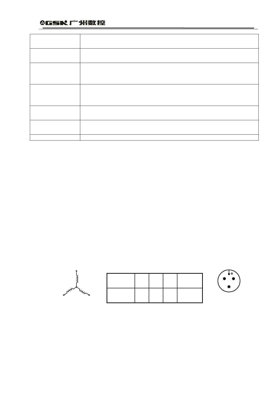
2) Terminal Explanation
(1) SJT Series of Motor Winding
U,V,W,PE terminal.The three winding phases of U, V and W of motor and the rack earth
are led out through a 4-core connector. The corresponding relationships are shown in
Table 8.2. U, V, W and rack earth are respectively connected with terminal U, V, W and
PE of the main return circuit.
Table 8.2 Motor Wiring
The lead wires of photoelectric encoder are led out through a 15-core connector. The
corresponding relationships are shown in Table 8.2. The lead wires shall be connected
with plugs of the driver feedback signals CN2 according to driver requirements.
Motor
Lead Wire
U V W
Rack
(Earth)
Socket
No.
2 3 4 1
4
3
1
2
W V
U
Diagram for Plugs
wire weldin
area