DA98D User Manual
55
Table 8.3 Encoder Wiring
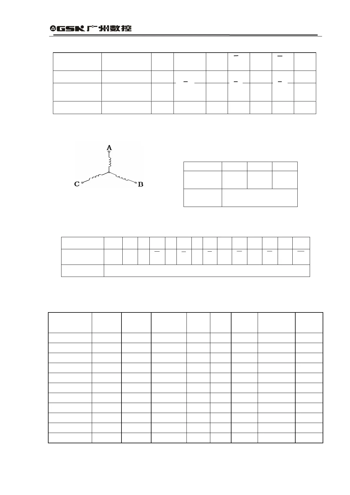
(2)ST Series of Motor Winding
Schematic diagram for motor winding is shown as follows:
A, B and C are lead-out terminals of winding.
Lead-out way: 4-core socket.
Table 8.4 Motor Wiring
Socket No. 2 3 4
Motor
Winding
A B C
Remark
One foot has ground
contact (rack)
Lead-out way of photoelectric encoder:15-core socket.
Table 8.5 Encoder Wiring
Marks 2 3 4 7 5 8 6 9 10 13 11 14 12 15
Lead-out foot
V
CC
GND
A
A
B
B
Z
Z
U
U
V
V
W
W
Remark GND is one foot (rack) of the encoder power Vcc that has ground contact
(3) Specifications
Table 8.8 Specifications on SJT Series of Some Motors
Models
Power(kw)
Paris o
Electrodes
Rated
Torque(N.m)
Rated
Rotation
Rated
Current
Rotor
Inertia
cceleration
Time
Operating
Voltage
110SJT-M020E 0.6 4 2 3000 3.0 3.4×10
-4
52 220(300)
110SJT-M040D 1.0 4 4 2500 4.5 6.8×10
-4
45 220(300)
110SJT-M060D 1.5 4 6 2500 7.0 9.5×10
-4
42 220(300)
130SJT-M040D 1.0 4 4 2500 4.0 1.19×10
-3
80 220(300)
130SJT-M050D 1.3
4
5 2500 5.0 1.19×10
-3
64 220(300)
130SJT-M060D 1.5 4 6 2500 6.0 1.95×10
-3
82 220(300)
130SJT-M075D 1.88 4 7.5 2500 7.5 1.95×10
-3
66 220(300)
130SJT-M100B 1.5 4 10 1500 6.0 2.42×10
-3
38 220(300)
130SJT-M100D 2.5 4 10 2500 10.0 2.42×10
-3
63 220(300)
130SJT-M150B 2.3 4 15 1500 8.5 3.1×10
-3
33 220(300)
130SJT-M150D 3.9 4 15 2500 14.5 3.6×10
-3
63 220(300)
Note: The user shall make a special indication if he or she wants to order motor with
Lead Wires of
Encoder
Rack (Earth) V
CC
GND A
B
Z
Socket No. 1 2 3 4 7 5 8 6
Lead Wires of
Encoder
Z U
V
W
Plug No. 9 10 13 11 14 12 15
A
B
U
V
W