DA98D User Manual
20
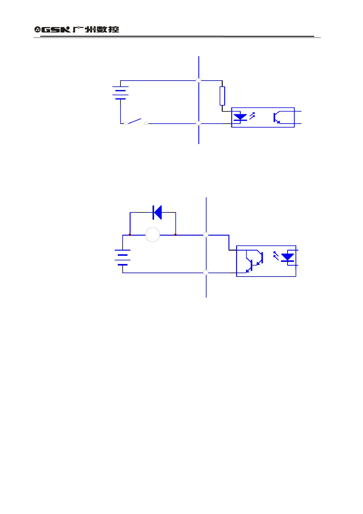
1) Switch Value Input Interface
Fig. 3.4 Type1 Switch Value Input Interface
(1) Power supply is provided by the user, DC12~24V, current≥100mA;
(2) Note: if the electrodes are reversely connected, the servo driver will not work.
2) Switch Value Output Interface
servo amplifier
max 25V
max 50mA
Fig. 3.5 Type2 Switch Value Ouput Interface
(1) The external power supply is provided by the user, but attention must be given to the case
that if electrodes of the power supply are reversely connected, the servo drive unit may be
damaged.
(2) The output is an open-circuit form of collector, with a maximal current of 50mA and a maximal
external power voltage of 25V. Therefore, the load of switch value output signal must satisfy
this limited requirement. If the limited requirement is surpassed or the output terminal is
directly connected with the power supply, the servo drive unit will be damaged;
(3) If the loads are inductive ones like relay, two sides of the load must be reversely connected in
parallel with the continuous current diode. If the continuous current diode is reversely
connected, the servo drive unit will be damaged.
3) Analog Input Interface
Driver Side
4.7K12~24V
SW
servo amplifier
COM+
Driver Sideface