DA98D User Manual
21
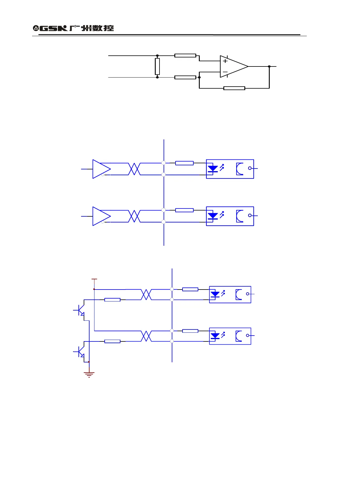
Fig. 3.6 Type4 Analog Command Input Interface
1. Input signal is connected with twisted-pair cable lines.
2. The circuit adopts the enlarged different-mode form, with an input resistance of 20K.
4) Pulse Output Interface
220
220
servo amplifier
PULS+
PULS-
SIGN+
SIGN-
Fig. 3.7 Type3 Differential Drive Mode of Pulse Input Interface
220
220
servo amplifier
PULS+
PULS-
SIGN+
SIGN-
R
R
VCC
Fig. 3.8 Type4 Uni-polar Drive Mode of Pulse Input Interface
(1) For correctly transmitting pulse data, it is recommended to adopt the differential drive mode;
(2) Under differential drive mode, AM26LS31 and MC3487 or similar cable driver of RS422;
(3) The uni-polar drive mode will reduce the motion frequency. According to the requirements on
the pulse amount input circuit: driving current 10~15mA and limited maximal external power
voltage of 25V, empirical data are as follows: VCC=24V,R=1.3 ~ 2k;VCC=12V,R=510 ~
Driver Sideface
Driver Side
5
6
7
B