DA98D User Manual
22
820Ω;VCC=5V,R=82~120Ω.
(4) When adopting uni-polar drive mode, the external power supply will be provided by the user, but
attention must be given to the case that if the power electrodes are reversely connected, the
servo drive unit may be damaged.
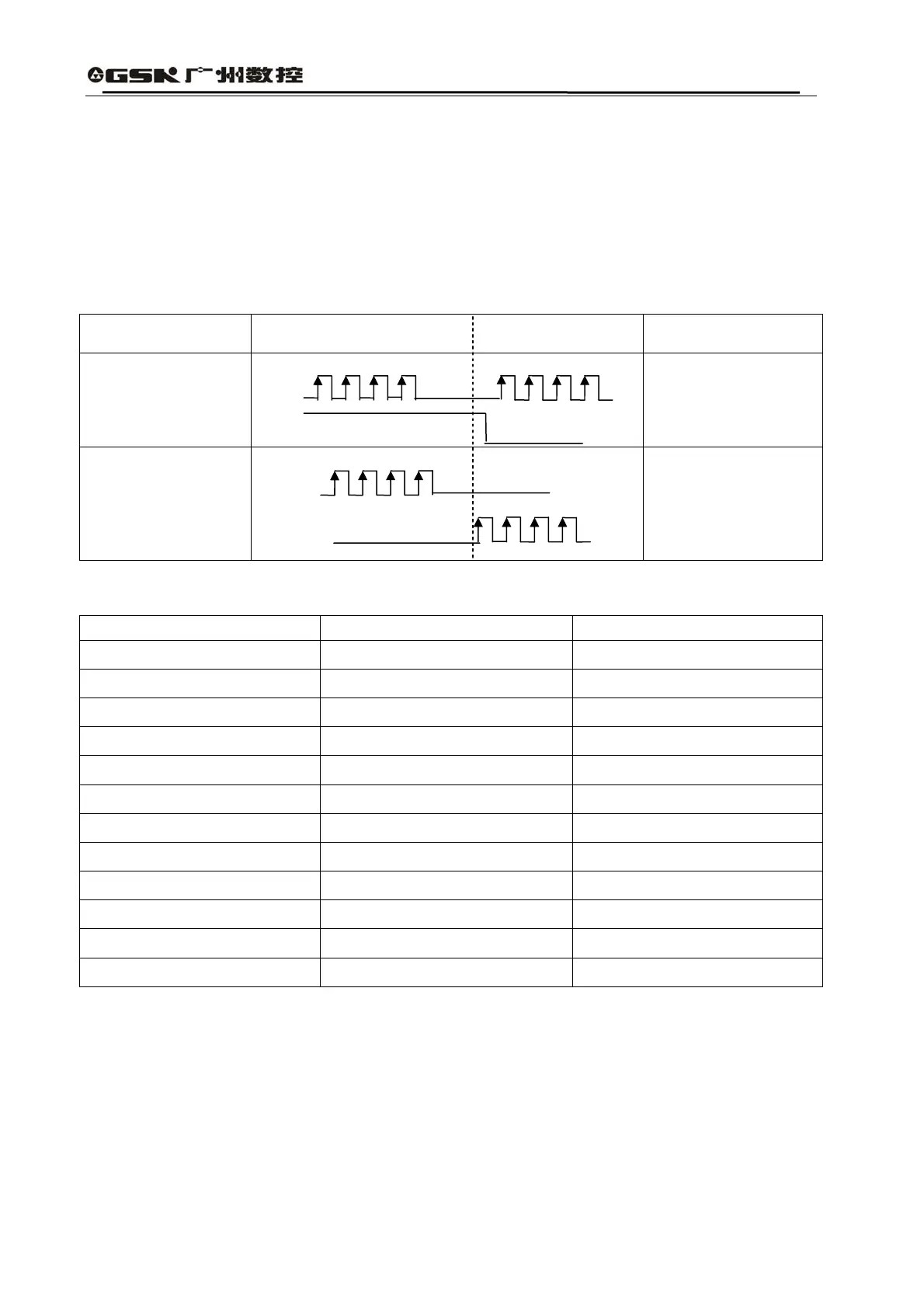
(5) Refer to Table 3.4 for details about the pulse input forms, in which the arrow means counting
trend. Table 3.5 shows the time sequence and parameters for pulse input.
Table 3.4 Pulse Input Forms
Forms of Pulse
Command
CCW CW Set Parameter Values
Symbol for Pulse
Train
PULS
SIGN
0
Command Pulse+
Symbol
CCW Pulse Train
CW Pulse Train
PULS
SIGN
1
CCW Pulse/CCW
Pulse
Table 3.5 Time sequence Parameters for Pulse Input
Parameter Differential Drive Input Uni-polar Drive Input
t
ck
>2μS >5μS
t
h
>1μS >2.5μS
t
l
>1μS >2.5μS
t
rh
<0.2μS <0.3μS
t
rl
<0.2μS <0.3μS
t
s
>1μS >2.5μS
t
qck
>8μS >10μS
t
qh
>4μS >5μS
t
ql
>4μS >5μS
t
qrh
<0.2μS <0.3μS
t
qrl
<0.2μS <0.3μS
t
qs
>1μS >2.5μS