DA98D User Manual
23
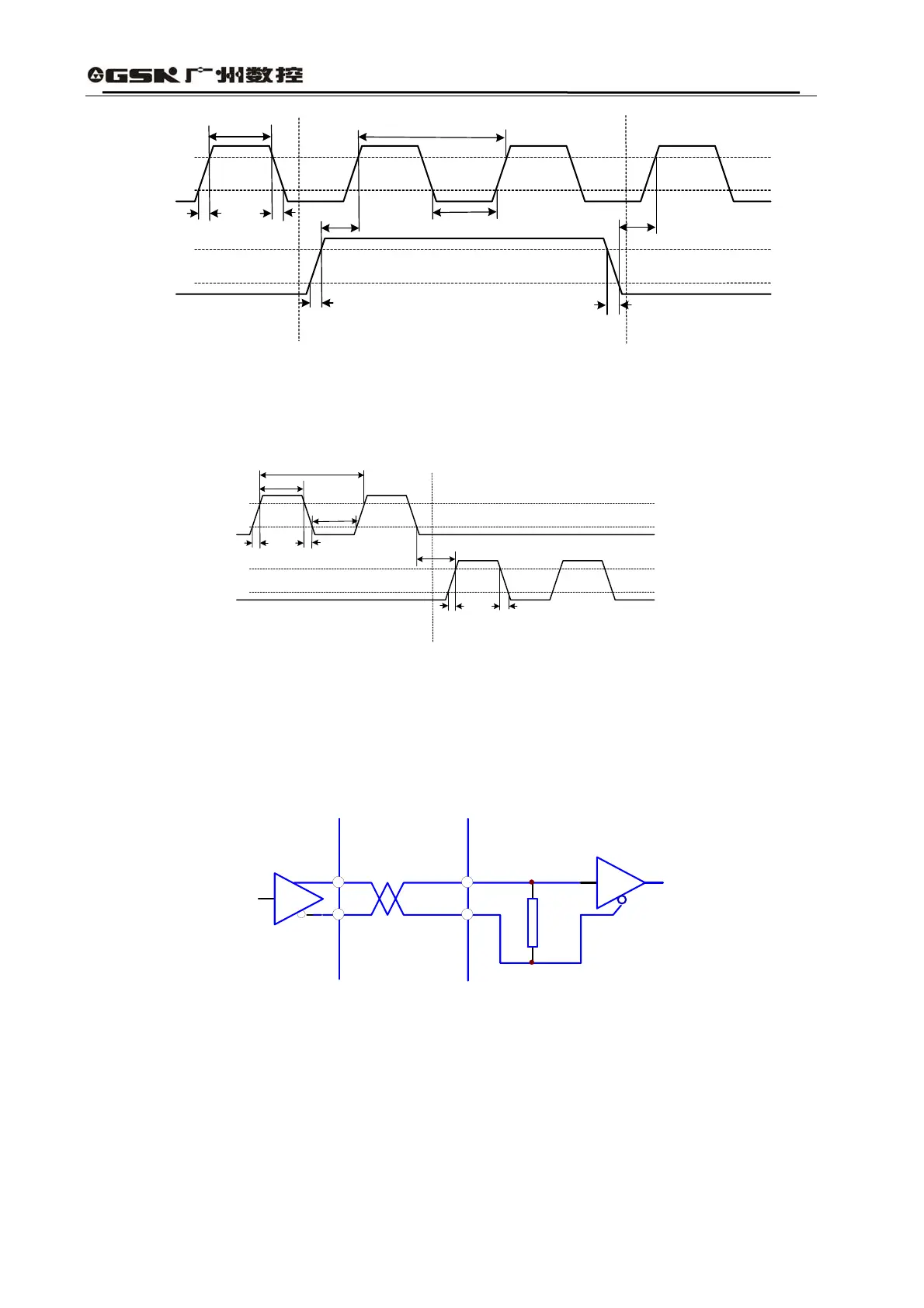
t
h
t
l
t
rh
t
rl
t
s
t
s
t
ck
t
rh
t
rl
90%
90%
10%
10%
CW
CW
CCW
PULS
SIGN
Fig. 3.9 Time sequence Diagram for Pulse+Symbol Input Interface (Maximal Pulse
Frequency:500kHz)
t
h
t
l
t
rh
t
rl
t
s
t
ck
t
rh
t
rl
10%
10%
90%
90%
CCW
CW
PULS
SIGN
Fig. 3.10 Time sequence for CCW Pulse/CW Pulse Input Interface(Maximal Pulse
Frequency:500kHz)
4) Driver Speed Signal Output Interface
servo amplifierservo motor
X+
X-
X=A,B,Z,U,V,W
AM26LS32
Fig. 3.11 Type5 Driver Speed Signal Output Interface
5) Input Interface for Servo Driver’s Photoelectric Encoder
Driver Side