DA98D User Manual
42
by 5.
Note 3:Control mode: 0---position control; 2---speed control;3---speed trial operation;
3---JOG operation;4---encoder zero adjusting;5---open-loop operation.
Note 4:If the displayed number reach 6 digits (like 123456), the hint characters will not
be shown.
Note 5:Position command pulse frequency is the actual pulse frequency before being
multiplied by the input electronic gear, with a minimal unit of 0.1kHz.
Forward-direction display stands for positive number and reverse-position
display for negative number.
Note 6:The calculation method for motor current I is :
)(
3
2
222
WVU
IIII ++=
Note 7:Absolute position of rotor during one round stands for the position of rotor in
relative to stator during the round. One round is taken as a cycle, ranging from 0
to 9999.
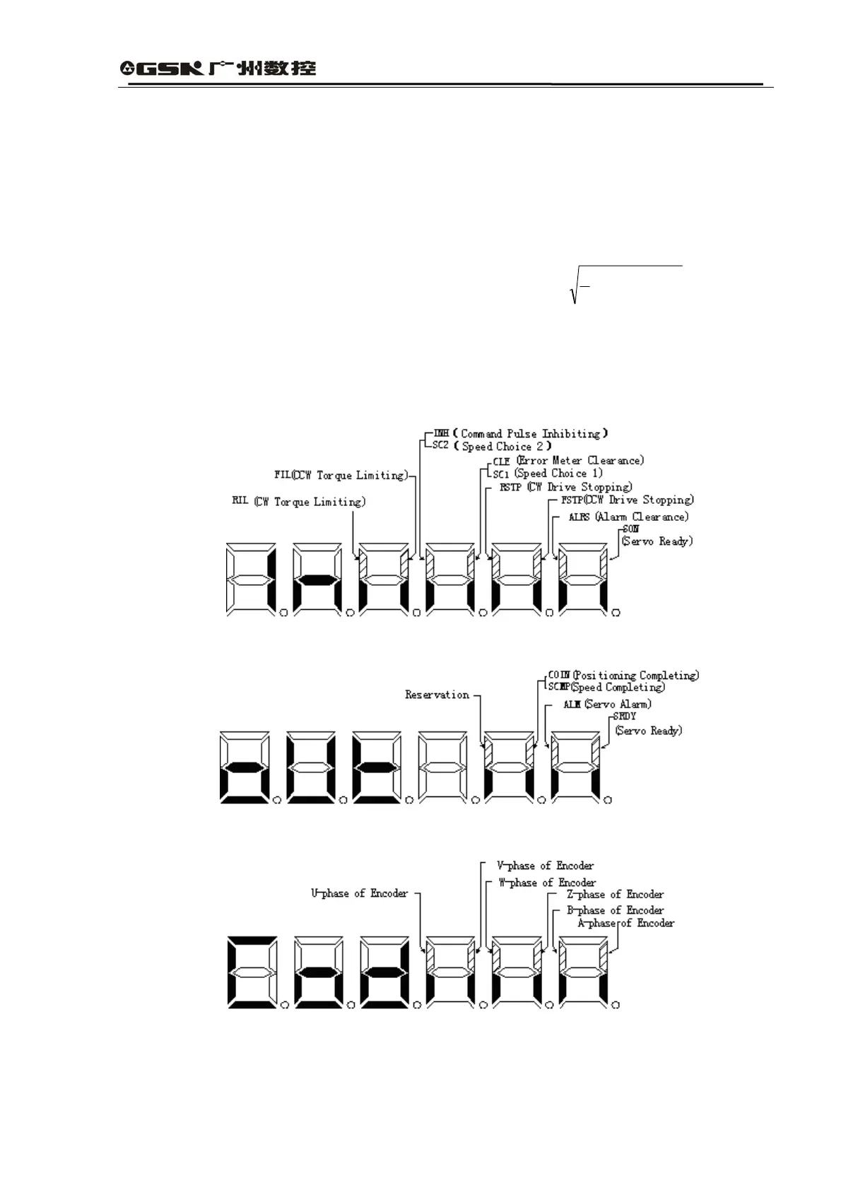
Note 8:Input terminal is shown in Fig. 6.3; the output terminal is shown in Fig. 6.4; and
encoder signal is shown in Fig. 6.5
Fig. 6.3 Input Terminal Display (dot shining means ON and stop shining means OFF)
Fig. 6.4 Output Terminal Display (dot shining means ON and stop shining means OFF)
Fig. 6.5 Encoder Signal Display (dot shining means ON and stop shining means OFF)
Note 1:Operation states are expressed as: