DA98D User Manual
52
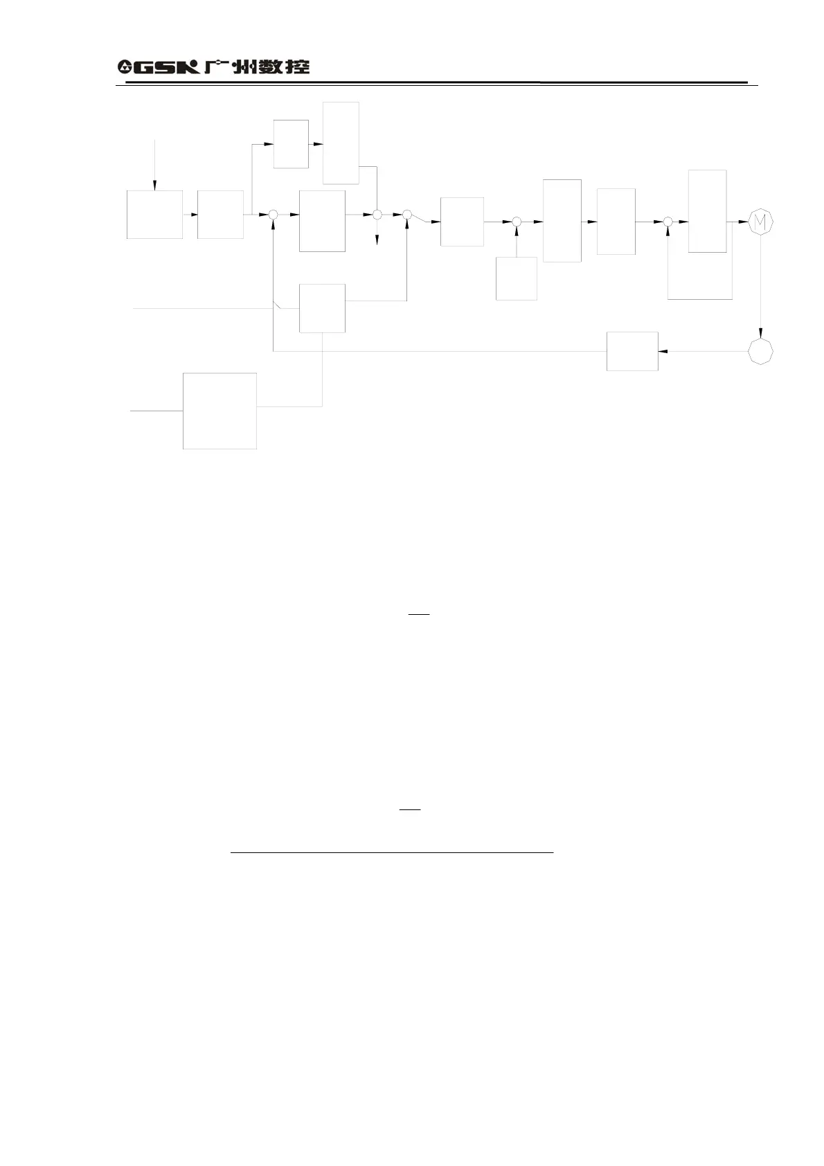
No.61
No.60
No.64No.6
No.5
No.41
No.40
No.4
No.47
No.9
No.12
No.13No.14
Four times
frequency
Time
constant
of current
proportional
gain integral
Current
command
low pass
filter
Speed
calculation
Time
constant
of speed
proportional
gain integral
Analog speed
command gain
External analog
voltage
No.43
Acceleration
/deceleration
time
Feed-
forward
low pass
filter
Feed-
forward
Position
proportional
gain
Electronic
gear
Pulse input
form
Position command
-
+
-
+
-
+
-
+
PG
Fig. 7.4 Chart for Adjustment in Basic Parameters
3) Position Resolution and Electronic Gear Position
Position resolution (one pulse itinerary l△ ) is determined by itinerary per round of servo
motor S and feedback pulse per round of encoder Pt△ , as expressed in the following calculation
formula:
l=△
Pt
S
In which,
l△ : one pulse itinerary (mm);
S:△ one pulse itinerary (mm/round);
Pt: feedback pulse per round of encoder (pulses/round).
Since there is a four-time frequency circuit in the system, Pt=4×C, in which C is the line
number per round of encoder. In this system, C=2500 lines/round, so Pt=10000
pulses/round.
Command pulse can be converted into position control pulse after being multiplied by
electronic gear ratio G, so one command pulse itinerary l△ ﹡is expressed as:
l*=△
P
S
×G
In which, G=
rdenominatodivision frequency pulse Command
numeratordivision frequency pulse Command