EN
23
Operating manual
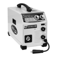
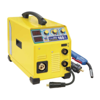
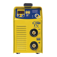
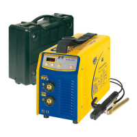
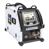
E1 - E2 - E3 GYS AUTO
Translation of the original
instructions
Open the power source’s hatch.
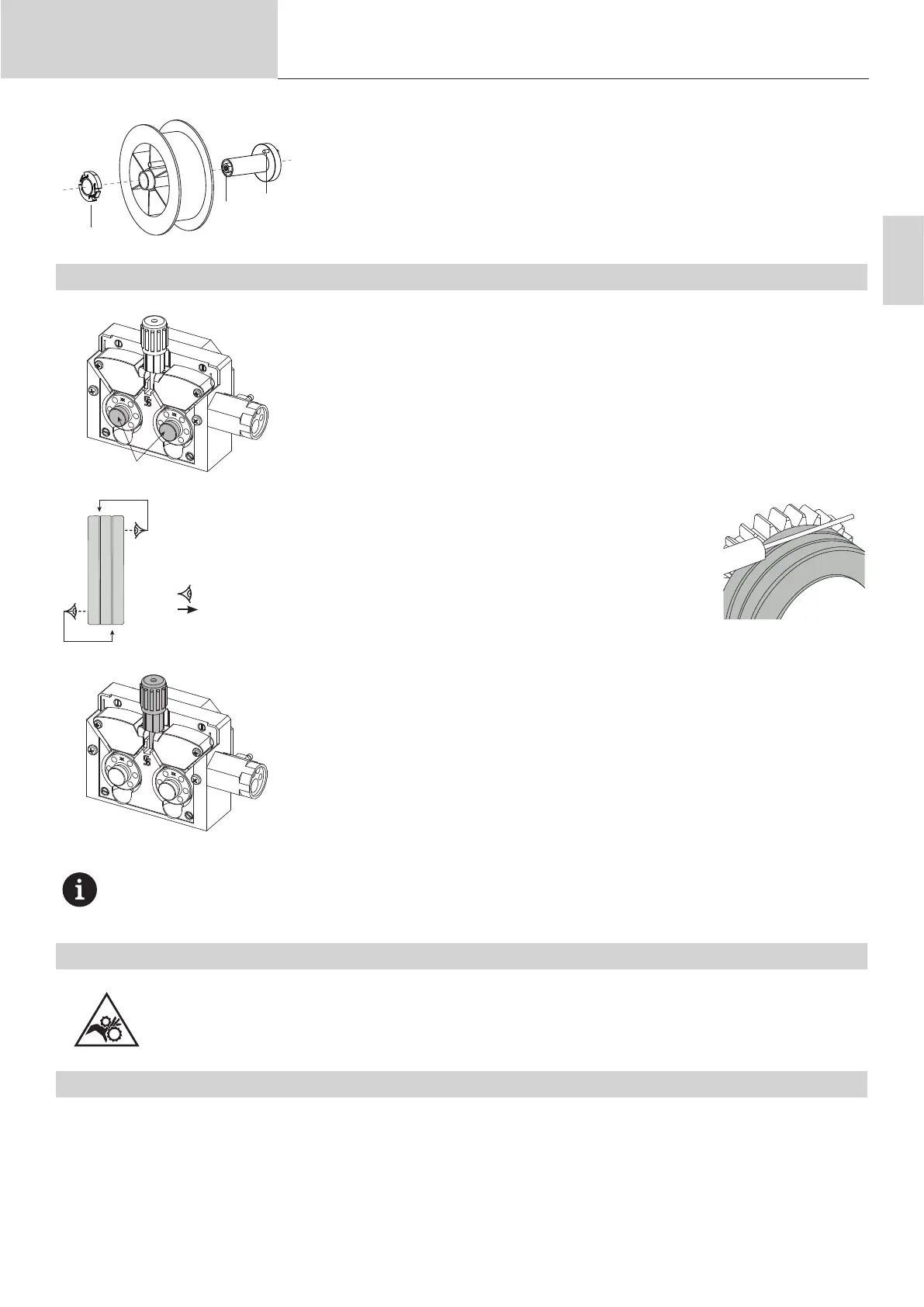
- Position the reel on its holder.
- Take into consideration the reel stands’s drive lug (c). To t a 200 mm reel, tighten the
plastic reel holder (a) to the maximum.
- Adjust the brake wheel (b) to prevent the non-moving spool from tangling the wire when
the welding stops. Do not over tighten as this will cause the power source to overheat.
LOADING THE FILLER WIRE
b
To change the rollers, do the following:
- Loosen the knob (a) to the maximum and lower it.
- Unlock the rollers by removing the retaining screws (b)
- Fit the appropriate drive rollers for your application and retighten the retaining screws.
The rollers supplied are double groove rollers :
- steel Ø 0.6/0.8 (E1 + E2 + E3)
- steel Ø 0.8/1.0 (E3)
- aluminium Ø 0.8/1.0 (E2 + E3).
- Check the inscription on the roller to ensure that the rollers are suitable for the wire diameter and
the wire material (for Ø 1.0 wire, use the Ø 1.0 groove).
- Use V-grooved rollers for steel and other hard wires.
- Use U-grooved rollers for aluminium and other soft, alloyed wires.
: visible inscription on the roller (example: 1.0)
: groove to be used
To install the wire, follow the steps below:
- Loosen the knob to the maximum and lower it.
- Insert the wire, then close the motor reel and tighten the knob as shown.
- Operate the motor via the trigger of the torch.
Notes:
- Too narrow a sheath can lead to unreeling issues and can lead to the overheating of the motor.
- The torch connection must also be properly tightened to prevent it from overheating.
- Ensure that neither the wire, nor the reel, touches the device’s mechanism, otherwise there is a danger of short-circuiting the ma-
chine.
RISK OF INJURY FROM MOVING COMPONENTS
The reels have moving parts that can trap hands, hair, clothing or tools causing injuries!
- Do not touch rotating, moving or driving parts of the machine!
• Ensure that the housing covers or protective covers remain fully closed when in operation.
• Do not wear gloves when threading the ller wire or changing the ller-wire’s spool.
SEMI-AUTOMATIC STEEL/STAINLESS STEEL WELDING (MAG MODE)
This machine can weld steel and stainless steel wire from Ø 0.6 to 1.0 mm (I-A).
E1 / E2 : The unit is supplied with Ø 0.6/0.8 rollers for steel or stainless steel as standard.
E3 : The unit is supplied with Ø 0.6/0.8 and Ø 0.8/1.0 rollers for steel or stainless steel as standard.
The contact tip, the sheave groove and the welding torch sheath are designed for this use.
To do this using steel requires a specic welding gas (Ar+CO2). The amount of CO2 may vary depending on the type of gas used. For stainless
steel, use a 2% CO2 mixture. When welding with pure CO2, it is necessary to connect a gas pre-heater to the gas cylinder. For specic gas issues,
please contact your gas distributor. The gas ow rate for steel is between 8 and 15 litres per minute depending on the surroundings. To measure the
gas ow rate at the torch outlet, it is recommended to use the optional ow meter (ref. 053939).