24
Operating manual
E1 - E2 - E3 GYS AUTO
Translation of the original
instructions
SEMI-AUTOMATIC ALUMINIUM WELDING (MIG MODE)
This machine can weld aluminium wire from Ø 0.8 to 1.2 mm (I-B) (Ø 1.2 mm, non-intensive welding).
E2 / E3 : The unit is supplied as standard with Ø 0.8/1.0 rollers for aluminium.
For use with aluminium, pure argon gas (Ar) is required. Seek advice from a gas distributor for a wide selection of gases. The gas ow rate for
aluminium is between 15 and 20 l/min depending on the surrounding environment and the welder’s experience.
The dierences between steel and aluminium processing are as follows:
- Use specic rollers for aluminium welding.
- Put minimum pressure on the motorised reel’s pressure rollers so as not to crush the thread.
- Only use the capillary tube (for guiding the wire between the feed rollers and the EURO connector) for steel/stainless steel welding (I-B)
- Use a special aluminium torch. This aluminium torch has a Teon coating to reduce friction. DO NOT cut away the coating at the tip of the connector!
This coating is used to guide the wire from the rollers.
- Contact tips: use a SPECIAL aluminium contact tip that matches the wire’s diameter.
When using red or blue sheathing (for aluminium welding), it is recommended to use the accessory 90950 (I-C). This
stainless steel sheath guide improves the centering of the sheath and facilitates the ow of the wire.
Video
SEMI-AUTOMATIC WELDING IN CUSI AND CUAL (SOLDERING MODE)
The machine can weld CuSi and CuAl wire from Ø 0.8 to 1.0 mm.
In the same way as with steel, a capillary tube must be set up and a torch with a steel sheath must be used. For brazing, pure argon (Ar) should be
used..
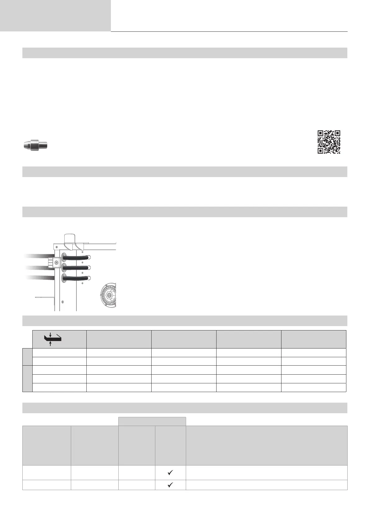
GAS SUPPLY
Bulkhead connector : E2 / E3
- Fit a suitable pressure regulator to the gas cylinder. Connect to the machine with the hose(s) sup-
plied, see diagram on page 6. Fit the hose clamps to prevent leaks.
- Ensure that the gas cylinder is held securely in place with a chain attached to the power source.
- Set the gas ow rate by adjusting the dial on the pressure regulator.
NB: To adjust the gas ow rate more easily, use the rollers on the motorised spool by pulling the trigger
on the torch (loosen the brake wheel on the motorised reel so that no wire is drawn in). Maximum gas
pressure: 0.5 MPa (5 bar).
This procedure does not apply to welding in «No Gas» mode.
RECOMMENDED COMBINATIONS
(mm)
Current (A) Ø Wire (mm) Ø Nozzle (mm) Flow (L/min)
MIG
0.8-2 20-100 0.8 12 10-12
2-4 100-200 1.0 12-15 12-15
MAG
0.6-1.5 15-80 0.6 12 8-10
1.5-3 80-150 0.8 12-15 10-12
3-8 150-300 1.0/1.2 15-16 12-15
MIG / MAG (GMAW/FCAW) WELDING MODE
Welding processes
Settings Settings
Manual
Synergies
(pre-installed
user settings)
Torque
material/gas
- Fe Ar 15% CO
2
- ...
-
Choice of the material to be welded.
Synergic welding parameters
Wire diameter Ø 0.6 > Ø 1.2 mm - Choice of wire diameter