2-14
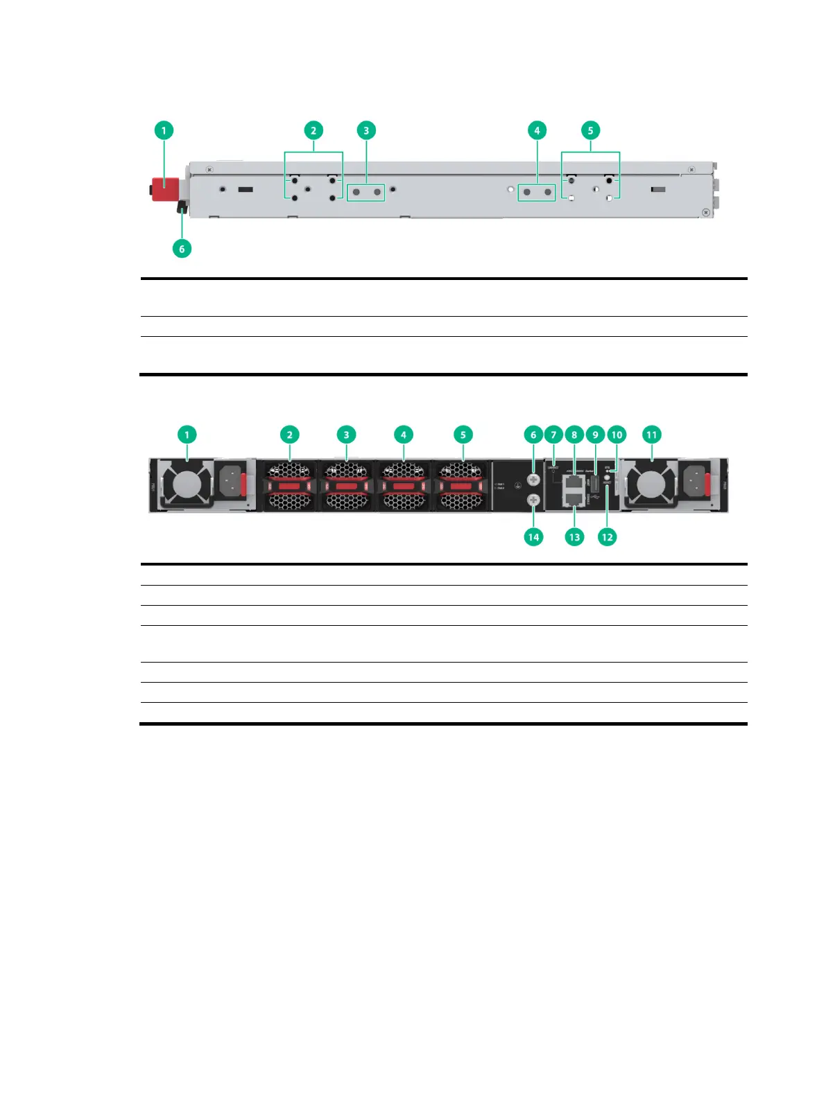
Figure2-5 LS-6850-56HF-H3 left panel
(1) Power module latch
(2) Mounting bracket installation holes at the power
(5) Mounting bracket installation holes at the port
(6) Power module handle
Figure2-6 LS-6850-56HF-H3 rear panel
(7) Copper management Ethernet port LED
(8) Copper management Ethernet port
(10) System status LED (SYS)
The LS-6850-56HF-H3 switch comes with power module slot PWR1 empty and power module slot
PWR2 installed with a filler panel. You can install one or two power modules for the switch as needed.
In Figure2-6, two SW-A-PSR550-12A-B power modules are installed in the power module slots.
The LS-6850-56HF-H3 switch comes with the four fan tray slots empty. You must install four fan trays
of the same model for the switch. In Figure2-6, four FAN-40B-1-C fan trays are installed in the fan
tray slots.
The LS-6850-56HF-H3 switch provides a reset button on the rear panel for you to reset the switch.
The LS-6850-56HF-H3 switch provides one grounding point on the rear panel and two grounding
points on the side panel. The primary grounding point has a grounding sign. As a best practice, use a
grounding point on the rear panel.

 Loading...


