11-2
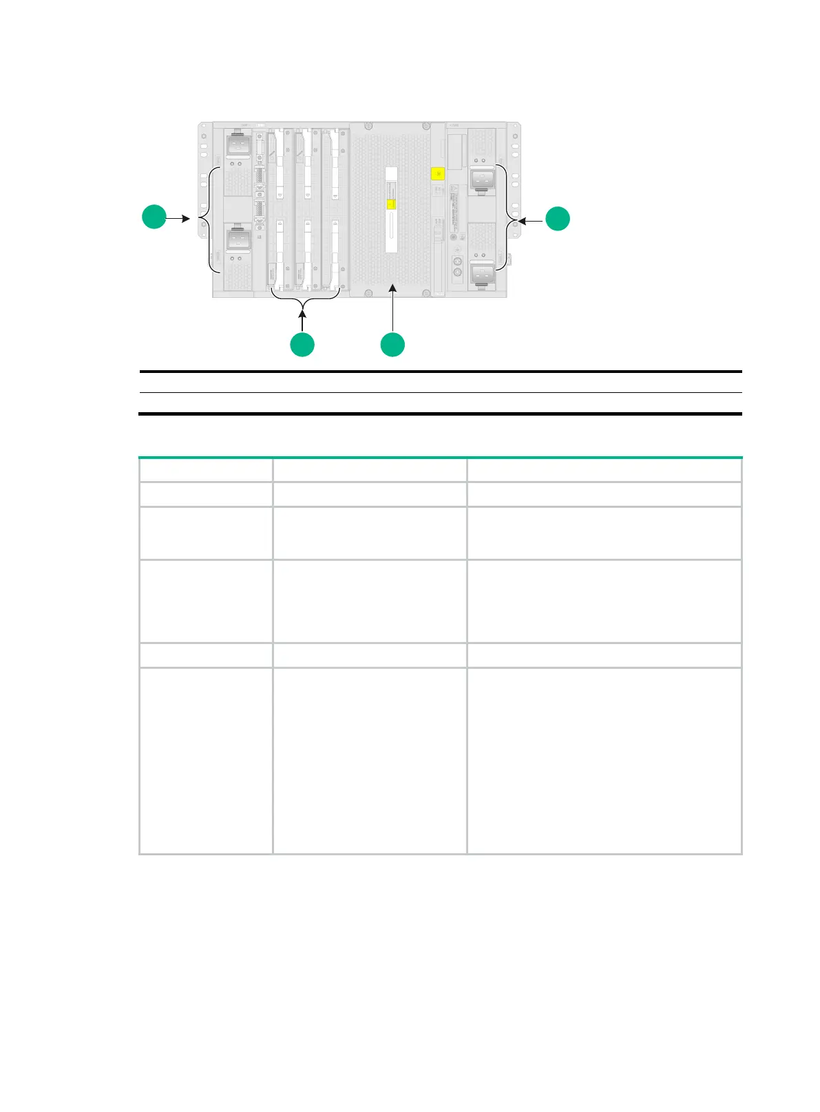
Figure11-2 Rear view
(5) Switching fabric module section
Table11-2 Descriptions for the M9000-X06/M9000-AI-X06 sections
MPU section Slots 4 and 5 N/A
Interface switch
module section
Slots 0 to 3
An interface switch module provides two slots
in which you can install firewall modules or
interface modules.
Power supply section
Power supply slots PWR1 to
PWR4
• Determine the power supply model based
on power distribution.
• Determine the number of power supplies
based on the power requirement of the
device.
Fan tray section Fan tray slots FAN1 and FAN2 N/A
Switching fabric
module section
Slots 6 to 11
• Slot numbers of switching fabric modules
are located at the top left corner and lower
right corner of the switching fabric module
section.
• You can install switching fabric modules
only in slots 6 to 9.
• Install a minimum of one switching fabric
module if the device is installed with more
than one interface switch module. If the
device is installed with only one interface
switch module, you can choose to not
install any switching fabric modules.