11-4
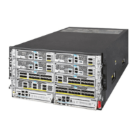
Table11-3 Descriptions for the M9000-X10/M9000-AI-X10 sections
MPU section Slots 0 and 1 N/A
Interface switch
module section
Slots 2 to 9
• An interface switch module provides two
slots in which you can install firewall
modules and interface modules.
• Interface modules and firewall modules
are not hot swappable. You must first
install them on an interface switch module
and then install the interface switch
module on the device.
Power supply section
Power supply slots PWR1 to
PWR8
• Determine the power supply model based
on power distribution.
• Determine the number of power supplies
based on the power requirement of the
device.
Fan tray section Fan tray slots FAN1 and FAN2 N/A
Switching fabric
module section
Slots 10 to 15
• Slot numbers of switching fabric modules
are located at the top left corner and lower
right corner of the switching fabric module
section.
• You can install switching fabric modules
only in slots 10 to 13.
• Install a minimum of one switching fabric
module on the device.