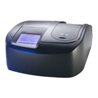
54
SECTION 5, continued
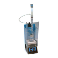
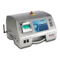
5.2.2 Automated Flow-Cell Kit (Low Pressure)
The Automated Low Pressure Flow-Cell Kit (Cat. No. 47450-00, 115 Vac or
47450-02, 230 Vac), uses a Flow Valve Module for control of sample flow
(see Figure 11). The kit contains a remote control cable used with the Model
2100AN Turbidimeter for automated operation. Refer to Section 5.2.1.1 and
Section 5.2.1.2 for assembly instructions. Omit step 5 in Section 5.2.1.1;the
Collection Drain Assembly is not provided with the Automated Flow-Cell Kit.
Figure 11 Automated Low Pressure Flow Cell
5.2.2.1 Connecting Inlet and Outlet Tubing
1. Cut a 53-cm (21") piece of clear,
1
/
8
" I.D. Tygon tubing. Install it between the
Flow-Cell Inlet Reservoir and Flow Valve Module inlet.
Note: Use the tubing supplied with the kit (or its equivalent). Tubing lengths are
approximate. Avoid using excess tubing because it causes air locking, and delays
measurement response time.
2. Cut a 31-cm (12") piece of clear,
1
/
8
" I.D. Tygon tubing. Install it between the
Flow Valve Module outlet and the Flow-Cell inlet.
3. Cut two 25-cm (10") pieces of clear,
1
/
8
" I.D. Tygon tubing. Install them
between the top and bottom Flow Cell drain fittings and the “Y” connector.
4. Cut a 11-cm (4") piece of clear,
1
/
8
" I.D. Tygon tubing. Connect one end to
the remaining “Y” connector. Pass the tubing under the support stand base
as illustrated in Figure 11. Install the
1
/
8
"x
1
/
4
" reducer on the other end of the
tubing.
5. Cut a 50-cm (20") piece of clear,
1
/
4
" I.D. Tygon tubing for the drain line.
Connect one end to the
1
/
8
"x
1
/
4
" reducer, and run the other end to a
suitable drain.
 Loading...