Install serial communications
Refer to Figure 8 on page
12 and Table 6 on page 12 to connect an
instrument with serial communication (RS485, RS232 or pulse).
Network wiring
Up to 32 instruments (12 K load each) can be included in a
RS485 (EIA-485) network with RS485 Modbus or FXB communication.
Use a high-grade wire for serial communications such as Belden 9841.
The manufacturer recommends that the length of the network is not
more than 1200 m (3937 ft).
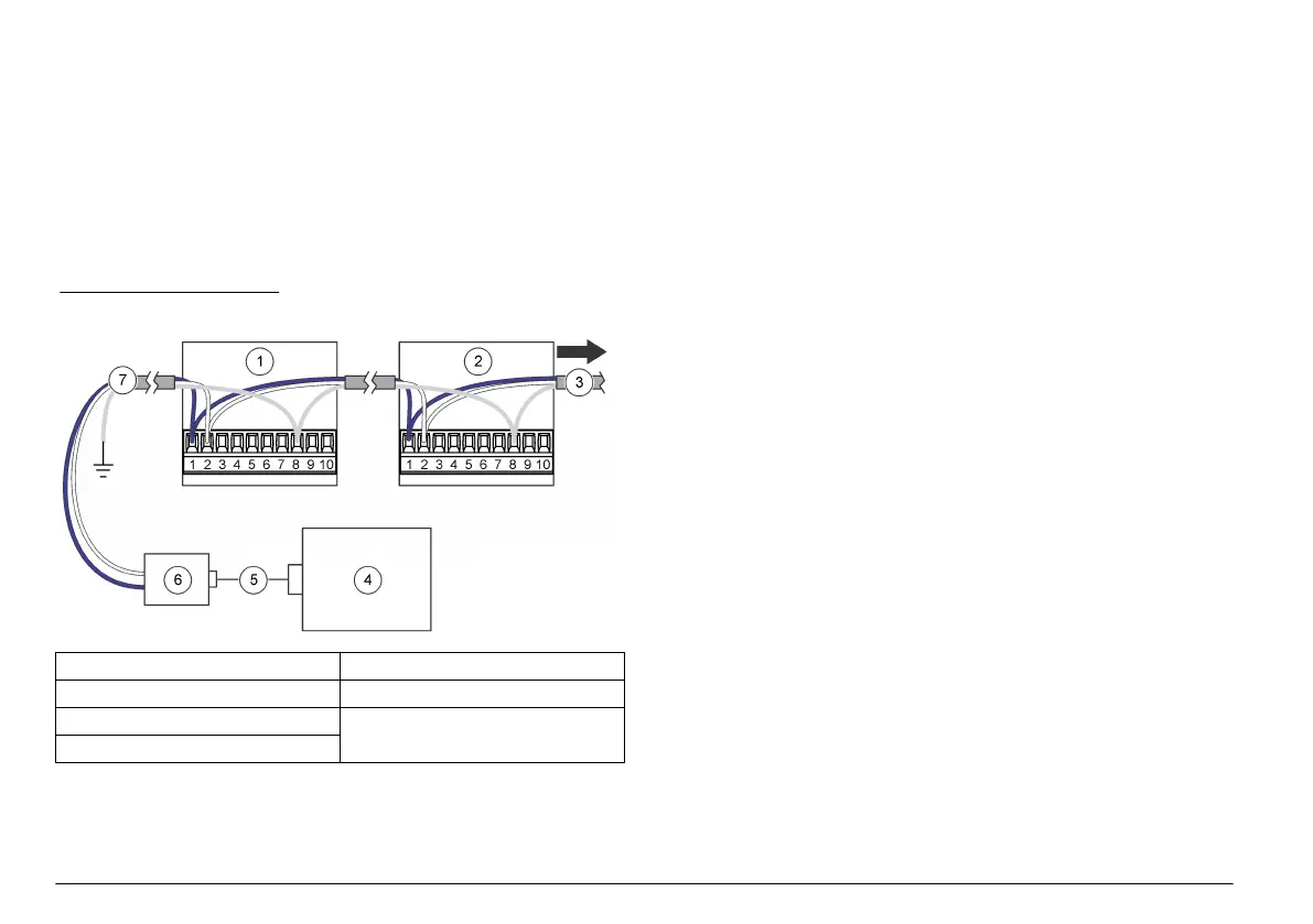
Figure 11 shows a typical network wiring diagram.
Figure 11 Network wiring
1 Particle counter 5 Cable
2 Particle counter 6 RS232 to RS485 converter
3 To additional particle counters 7 Network cable
4 PC
Connect to the Ethernet
Connect
instruments with Ethernet communication to an Ethernet
standard 10Base-T or 100Base-T network. Make sure that the wiring is
applicable for the speed of the network to prevent intermittent problems.
For this instrument, Ethernet standard 10Base-T is sufficient to transmit
data and is more tolerant of installation errors.
•
Length—100 m (328 ft) maximum, single wire length (repeaters can
be used to increase the distance)
• Repeaters—4 (maximum)
• Connector type—RJ45 (standard Ethernet wiring convention T-568B)
Connect the analog outputs
Connect instruments with the analog output feature to a data acquisition
system. Refer to Figure 8 on page 12 and Table 6 on page 12 for wiring
information.
When a +24 VDC power supply is used, the power supply can also be
used as the 4–20 mA loop power source if there is sufficient output for
the loop. Refer to Figure 12. Figure 13 shows the maximum limit of total
loop resistance (load and wiring combined) that is allowed.
Instruments with the analog output feature send a 4–20 mA signal that is
proportional to the number of counts in a given sampling time. The
analog outputs are updated at the end of each sample period. A data
acquisition system receives the signal. Instruments with the analog
output feature can have two or four channel sizes. Analog units cannot
be used in a network configuration.
Use the setup utility software to set the maximum number of counts that
correspond to the 20 mA signal. Refer to Configure the instrument
on page 17.
When power is applied, the analog outputs on the channels is 4 mA.
When power is removed or there is a sensor failure or flow failure, the
analog output on the channels is less than 2 mA. If a channel is disabled
by the user, the channel output is less than 2 mA. Any signal less than
4 mA (zero count value) causes a negative number in the data
acquisition system which identifies that there is a problem with the signal
from the instrument.
Configure the central monitoring software to alarm on any signal less
than 4 mA (zero count value) to get a sensor, flow or power loss alarm
as necessary.
14 English
 Loading...