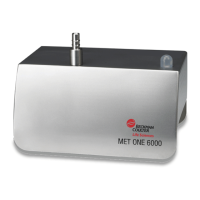
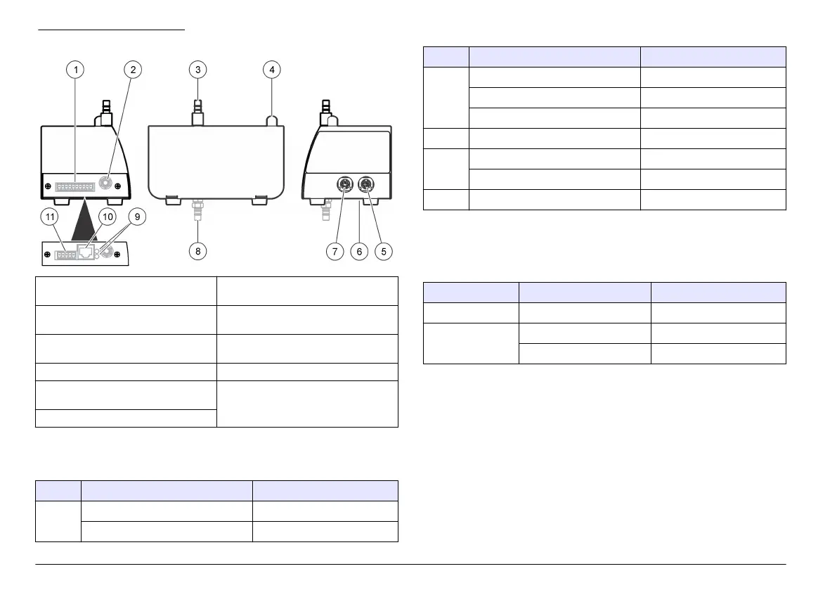
Figure 1 Product overview
1 Power input and communication
connector, 10-pin
1
7 Relative humidity (RH) and
temperature sensor port
2 Vacuum source fitting (or quick-
connect fitting)
8 Vacuum source fitting (alternate
location)
3 Sample air inlet fitting 9 Connection indicator lights
2
(Table 2)
4 Status indicator light (Table 1) 10 Ethernet RJ45 connector
2
5 Service port and optional light stack
port
11 Power input connector, 5-pin
2
6 DIP switch, network address
1
1
All units except Ethernet
2
Ethernet units only
Table 1 Status indicator light
Color Indication System status
Green Flashing (3 seconds) Normal, sampling
On Normal, not sampling
Table 1 Status indicator light (continued)
Color Indication System status
Blue On Sensor failure
One short flash, one long flash Air flow failure
Flashing Communication failure
Red On or flashing Count alarm
Yellow On Initialization
Flashing Count alert
1
Purple Flashing Setup utility is being used
1
The user-supplied central monitoring software can be used to make the yellow
light flash when a count alert occurs with ModBus protocol, not FX protocol.
The count alert settings are selected with the central monitoring software.
Table 2 Ethernet indicator lights
Color Indication Status
Yellow On Connected
Green Off 10Base-T
On 100Base-T
Isokinetic probe
For the best accuracy in laminar flow environments, always use the
supplied isokinetic probe with this
instrument. The velocity of air in the
probe is similar to that of a typical vertical or horizontal laminar flow
environment such as a clean room or clean hood. The supplied
isokinetic probe supplies the same vertical (or horizontal) flow speed of
the air in order to collect representative samples of the clean room
laminar flow for the instrument. Refer to Figure 2 for a comparison of
sampling with and without the isokinetic probe.
6 English
 Loading...